In this blog, I’ll walk you through the basic commissioning steps to get a brand-new Allen-Bradley PLC and HMI up and running. All the information covered here is also available in Rockwell’s help documentation, but I tried to distill out the most important bits to get you off the ground as fast as possible.
Before we start, you'll need all of the components networked together and powered on. You'll also need a PC with all the relevant Rockwell software installed. Once you've accomplished this, give yourself a pat on the back and read on!
Firmware Setup
Congratulations, you’ve just powered up your shiny new Allen-Bradley PLC for the first time. Now what? If it’s fresh out of the box, you’ll likely have to install the firmware. To do this, you’ll need a Rockwell tool called ControlFLASH. Believe me, it’s as exciting as the icon makes it look, just without the lightning bolts.
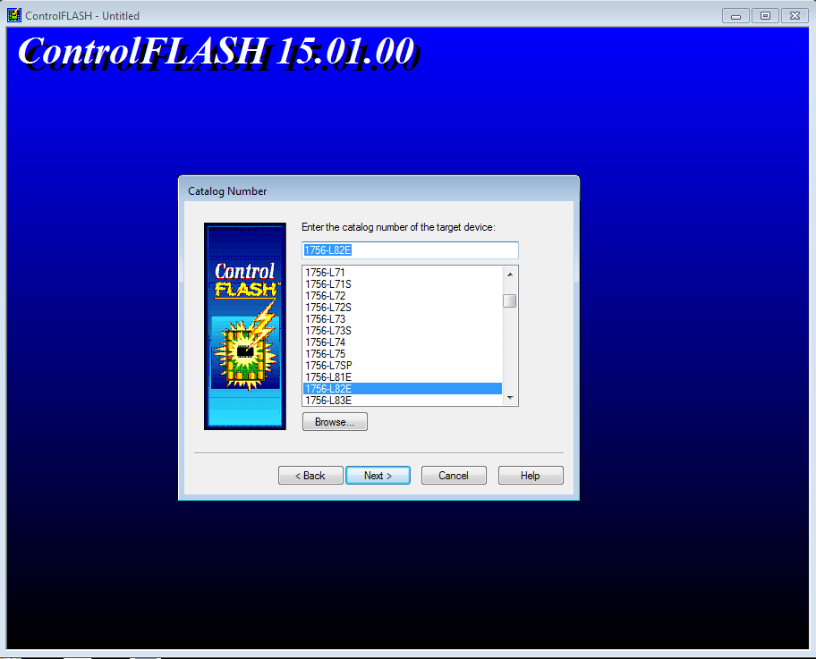
With an Ethernet cable connected directly between your PC and the PLC, follow the prompts to select your model number and firmware revision. Navigate to the PLC in RSLinx and click OK. Accept all the warnings that tell you not to do this on a live system. If you are doing this on a live system – STOP! When the firmware upgrade completes, the PLC will begin scrolling its MAC address across its display (if applicable). That means you’re ready to assign IP addresses.
Setting the PLC IP Address
The factory default for Allen-Bradley PLCs and many peripherals is to ship with BootP/DHCP enabled. However, DMC finds that best practice is to setup static IP addresses for all devices on the control network. This makes life much easier in the future, especially with integrating SCADA, remote access, and device troubleshooting. To disable BootP and give the PLC a static IP address, you’ll need another Rockwell tool called BootP DHCP EtherNet/IP CommissioningTool.
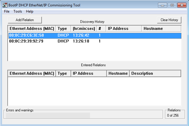
Locate your PLC by its MAC address and choose “Add Relation.” Next, right click on the PLC (now in the lower window pane) and choose “Disable BootP/DHCP.” Enter the desired network settings and click OK. Wait for the a successful confirmation message. It’s always a good idea to stop at this point and power cycle the system. If the PLC retains its IP address, go ahead and move on to the next step. If not, try this step again until the IP settings stick. If you’re having issues with the BootP/DCHP tool, check out Lillian’s blog post for tips.
Download your program
At this point, your PLC is ready for operation. With your program open in RSLogix, select “Who Active” from the “Communication” menu. This will bring up the familiar RSLinx view. Select your PLC at the IP address you just assigned and click Download. Remember to move the key on the front of the PLC to either "Remote" or "Program" before downloading.
Setup the HMI IP Address
This process varies from HMI to HMI, but the fundamentals are the same. Somewhere in the device setup menu, you’ll be able to type in your network settings. This is often a few layers deep in the device settings, but it is fairly straight forward. Note that many Rockwell HMIs require a power cycle after the network configuration is changed. Just like with the PLC, it’s always a good idea to verify that the settings were retained afterwards.
Setup HMI PLC Communication
Next, we need to tell the HMI where to find the PLC on the network. In FactoryTalk View Studio, the path to the PLC is configured in the “Communication Setup” menu of the project tree. The screenshots are taken from FactoryTalk View Studio Machine Edition.
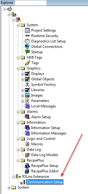
Double clicking the "Communicaiton Setup" icon brings up this window:
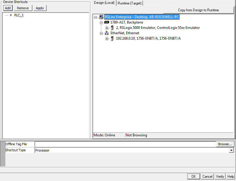
The leftmost pane of this window contains the “Device Shortcuts,” which is where you setup the path to any device your HMI needs to talk to. If you have more than 1 PLC in your project, add multiple device shortcuts. In this example, I just have one PLC, which I’ve named “PLC_1.” Best practice is to give the PLC a more descriptive name, such as "PlantHVAC_PLC." That way, an example tag on the HMI would read "[PlantHVAC_PLC]bExampleBooleanTag." For more information on tag linking, including global object parameters, check out these other blogs by Gina and Emily.
The right pane shows you all the available connections in RSLinx. Assuming you’ve configured your network adaptor correctly, you should be able to see the PLC at the IP address you gave it above. In my project for example, there are two PLCs that I can designate as “PLC_1”. One is an 1756-EBNT/A ControlLogix processor and the other is an emulated PLC. To choose the PLC path, I simply click on the processor I want and click OK.
But wait there’s a catch! Notice the two tabs at the top of the right pane: Design (Local) and Runtime (Target).
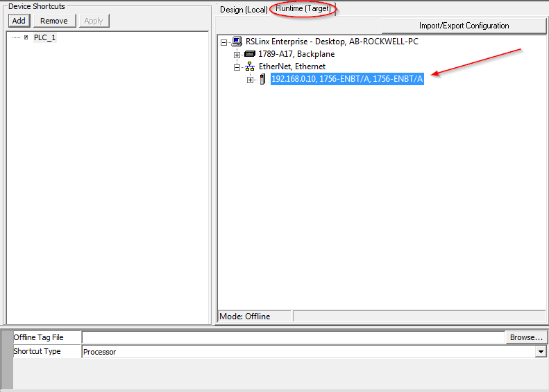
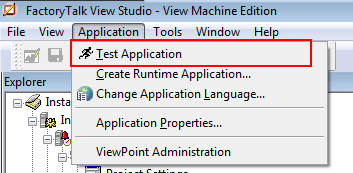
This is a really powerful feature that can sometimes be confusing to new users. These tabs allow you to assign two different PLCs to the same shortcut, depending on what "environment" you're running the HMI in. The design environment is FactoryTalk View Studio on your PC. This is the environment that opens when you click "Test Application" under the "Application" menu.
The other environment is the runtime environement. These settings are included in the actual machine edition runtime (.mer) file that you download to the HMI. This feature can be especially useful when you’re simulating features on your PC before deploying them to the physical PLC and HMI. However, it means that you have to be dilligent in setting the correct processor path for the right environment.If your communication settings seem correct and it still isn't working, the verify that the path to the PLC in the runtime environment is correct!
Once you've successfully mapped the PLC path in both environments, click OK and accept the confirmation messages.
Download to the HMI
Now that the program is configured, you’ll need to create a machine edition runtime file (.mer). The "Create Runtime Application" button is just under the "Test Application" button in the "Application" menu of FactoryTalk View Studio (see screenshot above). Save the file somewhere convinient and then open the "ME Transfer Utility." Locate the file you just created as the source file. Select the HMI in the RSLinx window and click Download.
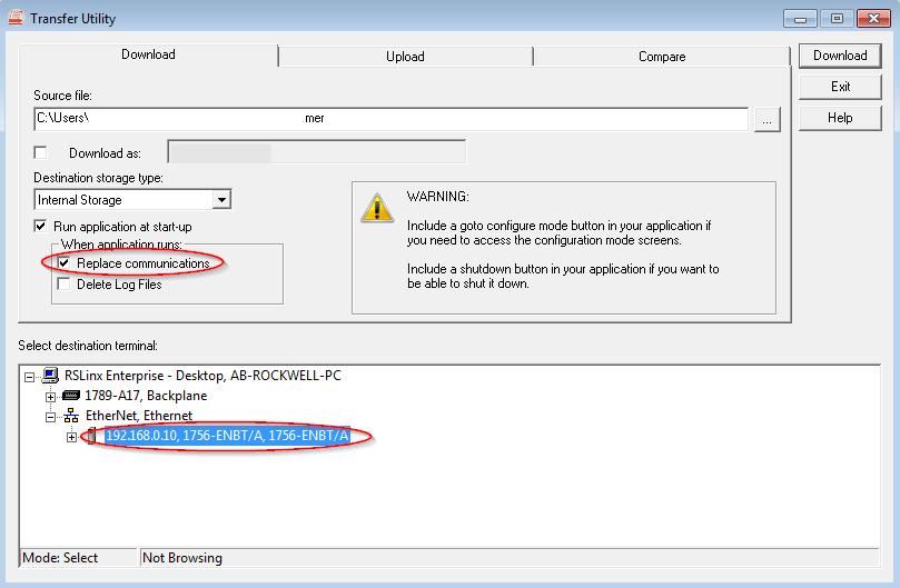
One option to take note of when downloading the runtime file is the “replace communications” checkbox. If you’ve just setup the path to the PLC, you must check this box to include the communication settings. If this isn't a new download and you're just making updates to an existing system, you might want to uncheck this box to eliminate the risk of messing up the communication paths.
Once the download finishes and the HMI restarts, you should be good to go. A good test is to modify a value in Controller Tags of RSLogix while online with the PLC and verify that the value updates on the HMI.
Next Steps
Hopefully this blog was helpful in getting your system up and running. This is by no means an exhaustive list of the settings and configuration options for PLC-HMI communication, but hopefully it got you off the ground. If you’re in need of further assistance, or if you’d like to learn more about DMC’s Rockwell programming expertise, please give us a call! Our team of experts is standing by, ready to get your next project rolling.