I’d like to take a more in-depth look at an underused feature in TIA Portal, and how to diagnose its associated issues in PLC logic rather than using online diagnostics. As mentioned in this blog, Topology setup in TIA Portal can provide an additional level of diagnostics information for networking and allows the use of more advanced configuration features.
Topology is easy to monitor while live on the PLC, but what if visibility is needed on network connections post commissioning? It’s not hard to imagine a fully commissioned machine being shipped to its final destination, only to be incorrectly networked on arrival. Being able to detect these errors without needing to go online with the PLC could provide a valuable diagnostic tool.
Using the standard Device Diagnostics tool in HMI gives you information on which modules are faulted but won’t provide much information detail other than “Error detected in Lower Level Component.”
For a system with a Topological Network, having a way to detect these faults in the PLC program can be very useful. This can be done by addressing Topological errors directly in the PLC using the ModuleStates Block.
ModuleStates Function Block
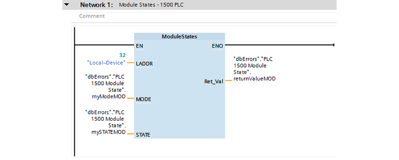
The key to being able to detect these errors within logic lies with the ModuleStates function block. This FB must be used within a cyclic interrupt OB. For this example, I also created a reusable UDT for the inputs to the block (leaving out a type for LADDR since there is better device visibility when just tied directly to the HW_Device data type associated to the module).
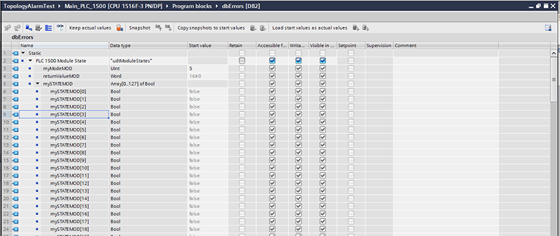
The STATE parameter outputs the status of the modules selected with the MODE parameter. For detecting errors in the modules, we’ll assign the mode as:
Mode 5: There is a problem in the modules. For example:
- Maintenance demanded or recommended
- Not accessible
- Not available
- Error occurred
With this configuration, we will see a TRUE anytime a module within a device has a problem. With that said, the first bit in the states array will always be true if any of the other bits are true.
From Siemens documentation:
If the status selected using MODE applies to a module, the following bits are set to "1":
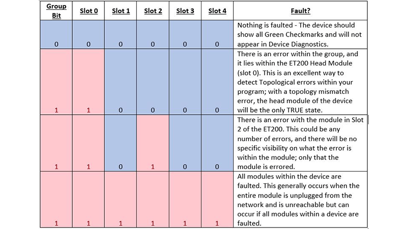
- Bit 0 = 1: Group display. The bit n of at least one module was set to "1".
- Bit n = 1: The status selected with MODE applies to the module in slot n-1 (example: bit 3 = slot 2).
The ET200 used in this example is configured as shown:
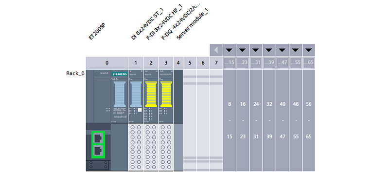
We would look at the first six (6) status bits on our States array (1 for the group and one for each module). See below to see a few examples of how these bits would look under various errored conditions.
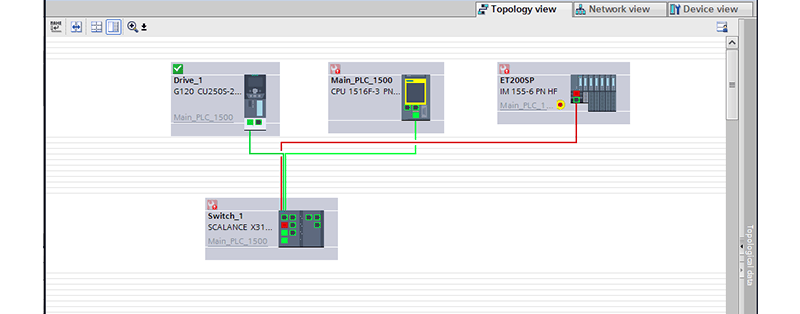
Topology Setup in TIA Portal – Setup #1: Direct Connection
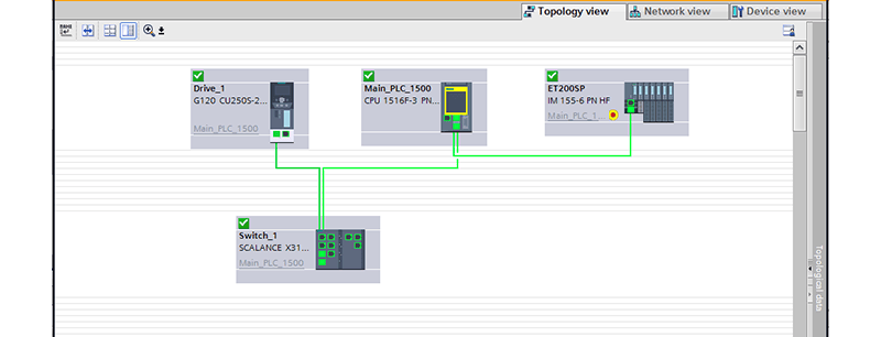
For this example, the topology is connected as shown above. The Main PLC and G120 drive are both connected through the switch, and the ET200SP is connected directly on the Main PLC. Any topology differences between the ET200a and the Main PLC will error only the two devices in question.
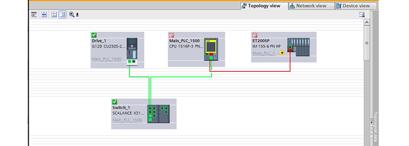
When a device has been networked incorrectly, the network line within the Topology view will turn red. In this case, the network cable running between the Main PLC and the ET200 has been plugged into the wrong port on the ET200.
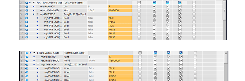
States of incorrectly networked devices
For clarity, the number of STATES shown below matches the number of modules within the device.
Topology Setup in TIA Portal – Setup #2: Connection Through a Switch
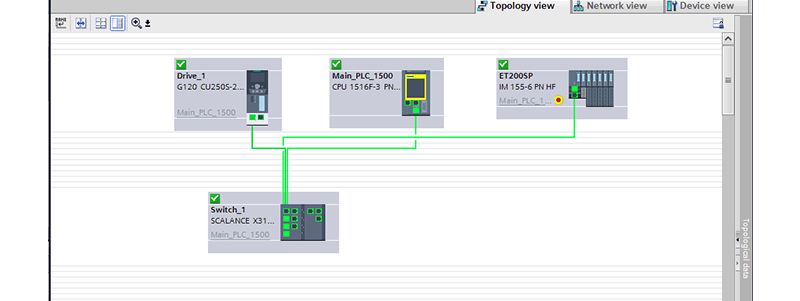
For the second example, the ET200SP is connected through the switch. Any topology differences between the ET200a and the Switch will result in an error on both devices as well as the main PLC.
States of incorrectly networked devices
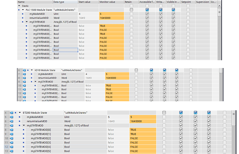
The head module of each of the errored devices is the only true state (other than the group fault, which indicates that something within the entire module as errored).
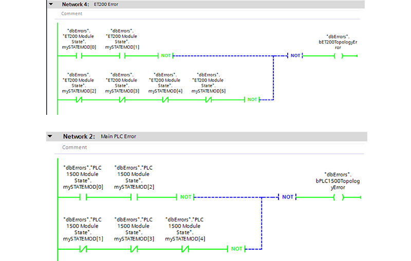
Identifying Topology Errors in Logic
We can then compare the states array of each device in logic to determine if a topology fault has occurred:
We can take that a step further and use the two devices to output another combined error. This can be used in the HMI to point to a connection where the topology error has occurred.
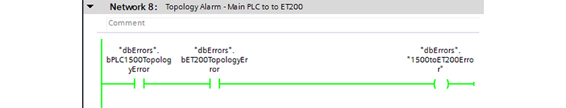
With a bit of work up front, troubleshooting any topology connection issues can be made much easier.
Learn more about DMC's Manufacturing Automation and Intelligence Services.
Contact us today for your next Automation project