I recently worked on a project using a GE PACsystems Rx3i PLC and a QuickPanel+ HMI. Throughout the course of the project, we learned some tricks to alarm handling in GE Proficy that I'd like to pass along. I'll first walk you through some of GE's nomenclature around alarms, and then we'll do a simple example. To get the most out of this blog, make sure you have GE Proficy pulled up and a blank Quickpanel+ project to follow along! I'm using Proficy Machine Edition v9.50 and 15" QuickPanel+.
Alarm Basics:
There are two main types of alarms on a QuickPanel+: Word Alarms and Bit Alarms.
- Word Alarms - An analog style alarm. An alarm message is displayed when a corresponding integer has the value specified.
- Bit Alarms - A digital on/off style alarm. An alarm message is displayed when the bit is in the specified state. The bit can either be a boolean or a specific bit in an integer. You can set these to trigger when high or low.
You can also assign variables to specific alarm groups. These allow you to organize your alarms on the HMI and only display the relevant alarms on a given screen. For example, if your system consists of multiple rooms, you may only want to display the alarms associated with the individual rooms on different screens. When setting up an alarm viewer object, you can choose which alarm groups it should display. You can also nest the alarm groups inside each other to allow multiple layers of organization. The alarm group is an attribute of the variable itself, so it's configured in the properties of the variable, under the "Alarms" tab.
A Simple Example
Let's walk through setting up some alarms of each type. Consider a mixing system that consists of a hopper and a large mixing drum. We'll assume we have a VFD driven motor running the mixer and two digital level sensors on the hopper.
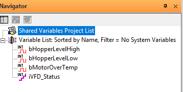
For the sake of simplicity, let's say we have two inputs for the VFD: a digital input that goes high when the motor is too hot and an integer input that tells us the status of the VFD (communicated over Ethernet, Modbus, or something similar). We'll also have two inputs for the hopper, a high and a low level. Under the "Variables" tab, we'll make variables for each alarm.
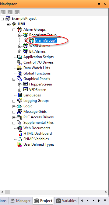
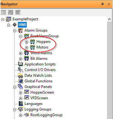
Next, let's make some alarm groups to help keep the alarms organized. Go to the "Project" tab and expand the "Alarm Groups" item. Right click on RootAlarmGroup and create a new one. We'll make two groups, Motors and Hoppers.
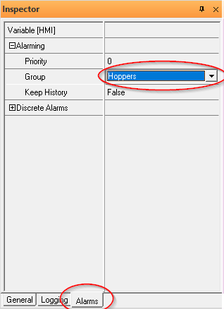
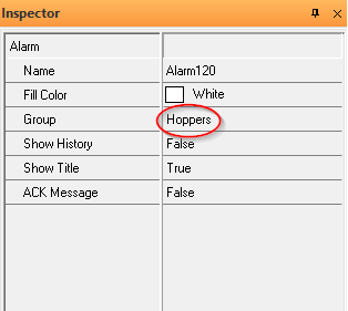
Now go back to the "Variables" tab. Highlight bHopperLevelHigh and go to the "Alarms" tab of the Inspector. Expand the "Alarming" object and modify the group to reference the Hoppers group. This assigns this variable to the Hoppers alarm group, meaning that it will only appear in alarm viewers that include that group. Repeat the same process for the rest of the variables, using the Motors group for the motor temperature and VFD status variables.
Hopper Alarms
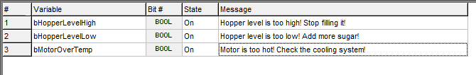
Now that the groups have been assigned, we need to tell the HMI when to trigger the alarms. Let's start with the hopper alarms. Back in the "Project" tab, right click on "Bit Alarms" and select "New Bit Alarm." This brings up an Excel-like spreadsheet where you can specify the variable, the state that should trigger the alarm, and the message that should be displayed. Select bHopperLevelHigh from the variable drop down. Since we want to alarm when the input is true, choose "On" for the state and add an appropriate message. Do the same for the low-level alarm and the motor over temperature alarm.
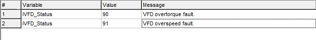
Notice that we can include all the alarms in the same alarm table, even though they're in separate alarm groups. Now let's set up the word alarm for the VFD status. Assume that the VFD manufacturer set up the iStatus value to be 90 for an overtorque fault and 91 for overspeed fault. Right click on "Word Alarms" and choose "New Word Alarm." Fill out the appropriate information just like we did for the bit alarms, but now specify the integer value that should trigger the alarm.
Note that Excel interfaces well with both of these editors. When we have a lot of alarms, we've found it really helpful to first generate the messages in Excel and then paste them into Proficy.
Lastly, we need to make the alarm viewers and link them to the correct groups. To demonstrate the nesting of alarm groups, let's put 3 alarm viewers on the same screen. I've changed the legend on each viewer to be "All Alarms," "Hopper Alarms," and "Motor Alarms."
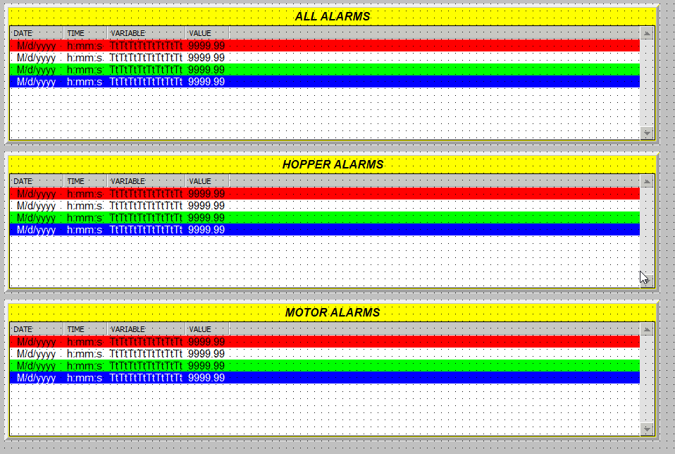
We can configure each alarm viewer to only display a specific alarm group. Select the alarm viewer and go to the "General" tab in the inspector window and edit the "Group" field. For the "All Alarms" viewer, choose the RootAlarmGroup. Since the RootAlarmGroup contains both the Hoppers and Motors groups, alarms assigned to either group will be displayed. Repeat the steps above for the other two-alarm viewers, but this time instead select the Hoppers and Motors groups.
And that's it! The alarms are now fully configured to display in the right places and in the right conditions.
If you need help with your GE or any other PLC programming projects, give us a call! Our team of expert engineers is standing by!
If you haven't already, check out my other blog on Rockwell FactoryTalk Alarms!