Modern PLCs are fast, but with only a few exceptions, they can only do one thing at a time. This is because PLCs are built around single-core processors. In this post, I’ll go over some of the low-level PLC concepts that both make PLCs versatile and limited in their capabilities.
Cyclic vs. Interrupt Code
Code on a PLC is called either cyclically or by an interrupt. Cyclic code runs start to finish repeatedly as fast as possible, so long as the CPU is not interrupted by an interrupt call. Interrupts pause the code currently running on CPU, call the interrupt code, and then once the interrupt code is complete, resume what the CPU was doing. Most PLCs can tie interrupts to cyclic timers, startup, value changes, and/or errors. Interrupts can also interrupt other interrupts if they are of a higher priority.
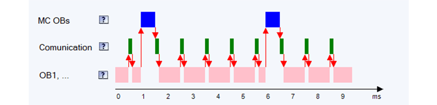
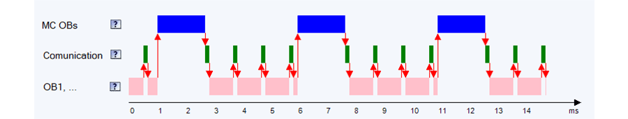
The diagram above shows what a PLC’s CPU spends its time doing. The pink represents cyclic code that would take the CPU 5ms to complete if it weren’t interrupted. The green represents the communication load on the CPU taking up to 0.15ms of every 1ms, and blue is the motion control code called every 5ms by a cyclic interrupt. In this example, the motion control interrupt is the highest priority, meaning it can interrupt communication and cyclic code.
Cyclic code is commonly referred to as the main PLC code. Siemens refers to cyclic code as a program cycle or OB1, and Allen-Bradley calls it a continues task. Interrupts, other organizational blocks in Siemens or event tasks in Allen-Bradley, allow the designer to specify precisely when the interrupt code should run in relation to an event or a timer.
For example, high-speed counters are typically tied to hardware interrupts, allowing a hardware input to increase the count in the PLC immediately. View this blog for examples of high-speed counters. This means that the high-speed counter can count multiple inputs before the PLCs main code has completed a full cycle. Similarly, PID control loops and motion control code are offend tied to cyclic interrupts, with varying cycle times. Physical systems that are slow to respond can be tied to cyclic interrupts with long cycles. This, in turn, reduces the CPU load. Systems that are quick to respond can be tied to much faster cycles allowing for tighter control, at the cost of CPU load.
Cycle Time
PLC cycle time is defined as the time it takes to run the cyclic code start to finish once with interrupts. Because of the number and frequency of interrupts between cycles, cycle times also very. In most cases, we are concerned with the maximum cycle time since this corresponds to how long it will take the PLC to respond. A general rule of thumb is to assume that the PLC could take as long as twice the maximum cycle time to respond. This means if we have a running signal indicator light, it could be up to twice the max cycle time between when the PLC gets the running signal and the light turns on.
Most PLCs monitor the cycle time and will alarm if the cycle time exceeds a maximum threshold. The specific threshold should be configured based on the application and the maximum acceptable response time of the PLC. Cycle times are particularly important in safety applications where the PLC’s response time can add to the response times of other components.
Reducing Cycle Time
There are a few methods to decrease the PLC's response time if cycle times must be reduced. Firstly, consider if the PLC’s CPU can be upgraded. A faster CPU will execute code faster and reduce the overall cycle time. This method is particularly effective for projects that have a lot of motion control and PID control loops, as these functions are generally very CPU intensive.
Siemens 1511 CPU (14.9ms Cycle Time)
Siemens 1517 CPU (6.3ms Cycle Time)

The next aspect to consider is the communication load. Communication load is defined as how much of the CPU’s time is spent communicating with other devices, and typically ranges from 15% to 50%. Upgrading the CPU can help reduce the communication load some, but for the most part, reducing communication load is a function of the communication method(s) and quantity. Consolidating the number of devices the PLC must communicate with and/or using communication methods with less overhead can both help but are often harder to implement.
Another method for reducing cycle time is optimizing the code itself. Moving pieces of code that do not have to run every cycle into cyclic or other interrupts can help reduce mean cycle times, but may not have much effect on the maximum cycle time. Moving code into interrupts can also make testing the cycle time more difficult as the interrupts may or may not occur in every cycle.
Monitoring Cycle Time
Siemens' S7 TIA Portal PLCS:
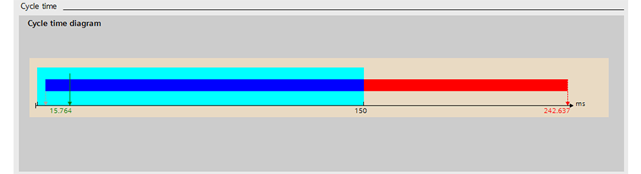
TIA Portal has a built-in tool that allows you to monitor the cycle time of a physical PLC or a simulation of the PLC. To monitor the cycle time, first, go online with the PLC, upload the PLCs code, and then open Online & Diagnostics. Under Diagnostics>Cycle time, you’ll see a bar chart with the current PLC cycle time. The light blue box represents the allowable cycle time, and a red bar indicates that cycle time has exceeded the maximum. This is shown in the diagram below.
To change the allowable cycle time, open the PLC’s Device configuration and under General>Cycle, update the maximum cycle time. You will have to be offline with the PLC to change this value and then redownload to the PLC for the change to take effect. Remember that the max observed cycle time may not be the actual max cycle time. This can happen if the code running on the PLC has many interrupts, or long and looping pieces of code called by interrupts.
Allen-Bradley and Other PLCs:
Finding the cycle time of other PLCs can be done more manually, although it’s no less relevant or useful for developing well-optimized code. The simplest way is to check the system time at the start of each cyclic call and compare the current system time to the previous system time. This method will include the overhead time the PLC takes to communicate and scan I/O. With a little more logic, you can easily find the min, max, and mean cycle times.
Understanding cycle time, cyclic calls, and interrupt calls is key to architecting successful PLC code and just one of the areas DMC excels at. Good architecture early on in a project can save time and allow the uses of more cost-effective hardware, while still meeting project requirements explicit and implicit.
Learn more about DMC's PLC Programming services and contact us to get started on your next PLC Programming project.