Rockwell’s HMI development software, Factory Talk View (FTV), is a notoriously powerful tool for HMI design with a wealth of valuable features. However, FTV is not always the most intuitive program to work with. Fortunately, Rockwell has also created Studio 5000 View Designer for the PanelView 5000 family of HMIs. View Designer is a design environment that feels intuitive and user-friendly while incorporating many of the features that make FTV so powerful.
In this tutorial, I will walk you through the process of linking a pop-up to an add-on graphic such that the tags associated with the graphic get passed along to the connected pop-up. In the end, we will be able to easily and simultaneously add a graphic and pop-up that allow for monitoring and control of a two-state valve. This result is highly modularized and enables valves to be added or removed from your project easily.
Add-on graphics are analogous to global objects in FTV in that they are a collection of graphic elements that can be instantiated multiple times within a project. If a change is made to the definition of an add-on graphic or pop-up, then it will propagate to all instances of those objects that are currently in the project. This ensures consistency across all displays and allows for changes to be pushed to the project fluidly without having to edit each individual instance of the graphic.
Initial Setup
Before you get started with your View Designer project, it’s important to have at least a basic framework for your project’s logic already laid out in Logix Designer. One of the first steps in creating a new View Designer Project is to link it to a Logix Designer Project. An ACD file can also be linked at any time via the project properties under the ‘References’ tab.
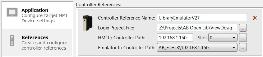
Once the Logix Project is linked, View Designer will have access to all tags, user-defined data types (UDT), and add-on instructions (AOI) that are present in the project.
When making reusable graphics, I advise you to have the UDTs and AOIs that you anticipate using in your project. Any changes to these tags and data types in Logix Designer will be reflected in the View Designer Project. However, one should be wary when making changes to existing data types as they might not be compatible with the existing View Designer Project after the changes. You must verify both the controller and the HMI project after making changes.
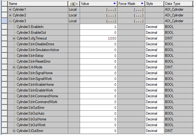
I’ve created a simple project containing three valves. Each valve is controlled by an AOI, which contains all the tags needed for our HMI display. Note that by constructing a modularized Logix Designer program, it follows that my View Designer program will also be highly modular. This makes for a more organized and easily reconfigurable project. Thanks to this compartmentalized architecture, I will only need to link a single tag to each of my graphics.
Making Reusable Graphics
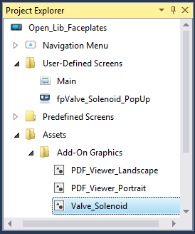
Once you’ve created your View Designer Project and linked a Logix Designer project, you’re ready to make your add-on graphic. In the Project Explorer in the top left of the screen, go to Assets > Add-On Graphics, right-click the Add-On Graphics folder and select New Add-On Graphic. You may right-click the new graphic and select to rename it. We’ll name our graphic Valve_Solenoid.
Double click the add-on graphic entry to begin editing it. Before we add graphical elements, let’s first establish our user-defined properties. User-defined properties are a lot like placeholder parameters in FTV, although they are a bit more intuitive to work with because they are represented by the name you assign them rather than a number.
To access UDTs and AOIs in the linked Logix Designer Project, click the ellipses button in the Data Type column, navigate to User-Defined properties, and select the desired data structure. As I noted earlier, our AOI contains all the needed tags, so we can link this one parameter rather than linking a dozen tags individually.
If you want a parameter in your AOI to be accessible in your HMI, then make sure to set its external access appropriately in Logix Designer. Also, note that InOut tags in an AOI cannot be configured for external access. If you want an InOut parameter to be accessible, you can map it to a local tag in the AOI and configure that for external access.
Now we’re ready to start adding graphical elements to our add-on. View Designer comes with a fantastic array of symbols and graphics in the default toolbox. We are looking for a symbol to represent a valve so we can enter ‘valve’ in the Toolbox search bar on the left side of the screen, and View Designer presents us with dozens of possible valve options. Here we are trying to create a very general valve faceplate, and so we will choose the simplest valve symbol available.
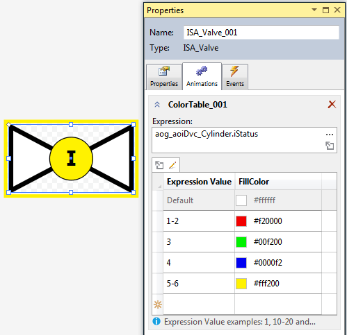
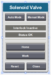
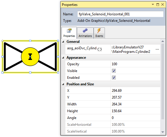
I’ve created a basic add-on graphic using the valve graphic and some other simple graphical elements. I’ve added a yellow rectangle to show when the valve is in manual mode and a circle to show when the valve is interlocked. I’ve also added an animation to the valve symbol, so it's color changes based on its status.
Pop-Ups and Base Properties
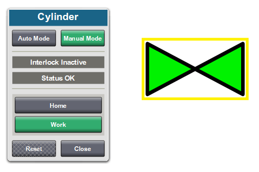
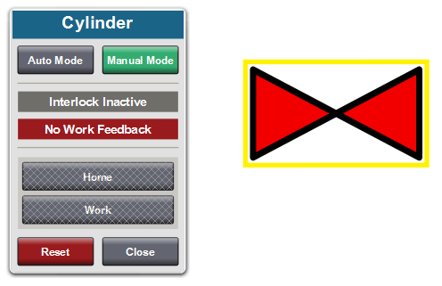
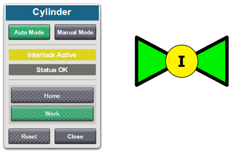
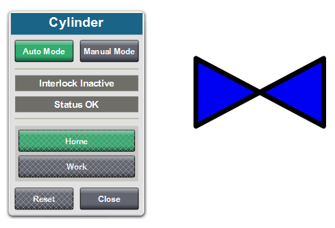
I’ve also created a pop-up that can display additional information on the valve and allows the operator to toggle between auto and manual modes and issue commands when the valve is in manual mode.
To make a pop-up, right-click the User-Defined Screens folder and select ‘New Pop-Up.’ Like the add-on graphic, this pop-up has the valve AOI as its only user-defined property. It should be noted that all user-defined properties in a pop-up need to be connected, either directly or indirectly, to an instance of the proper data type that exists within the Logix project.

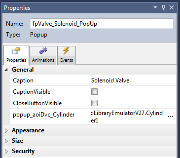
Below, I show the direct method of linking a tag instance to a pop-up. I’ve linked it to an instance of aoiDvc_Cylinder called cylinder1. This tag instance defined in the definition of the pop-up is called the Base Property. When configuring an event that opens the pop-up, you can choose whether the pop-up uses the Base Property or whether it’ll be linked to a different instance of the data type.
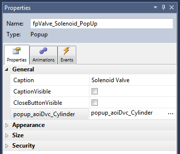
Next, I’ll show the indirect method of linking a base property. Here I’ve linked the user-defined property itself as the base property. When we add a navigation event that opens the pop-up, we’ll pass an instance of the cylinder AOI, and the pop-up will use this.
When using this method, you cannot use the base property of the pop-up since it isn’t an actual instance of the data type that exists on the PLC. Additionally, you will not be able to compile your project unless you have a navigation event somewhere that opens the pop-up and passes a valid tag to it. Otherwise, you’ll get errors saying that View Designer cannot find any of the properties linked to elements of your pop-up.
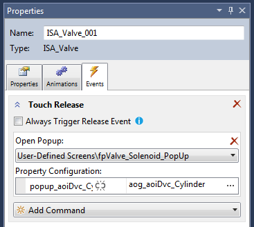
Now we’re going to go back to our add-on graphic and configure it to open our pop-up when the valve symbol is clicked. I add an event to the valve icon to open a pop-up when touched and under Property Configuration enter the user-defined property for the add-on graphic.
Now when the graphic is touched, it will pass the aoiDvc_Cylinder instance tied to it to the pop-up.
Using the Graphics
Now to add an instance of the graphic to our HMI, all we need to do is click and drag the graphic into a screen and link an aoiDvc_Cylinder tag from the PLC. Then, we're done!
Below are a few shots of the pop-up and graphic in action.
Final Tips
- The expression editor is a powerful tool that allows a high degree of configurability and specificity in your display. In this example, we only linked the exact value of a status tag to the valve color, but it could be used for much more complex displays. Keep this in mind when programming your HMI.
- Always be sure that your controller and HMI project can be verified after you make changes to AOIs, UDTs, and tags in RSLogix. Your tag binding expressions will not be altered in View Designer even if you altered the Logix tags linked to them.
- Compartmentalizing your code into UDTs and AOIs will make both the coding and HMI design experiences much more fluid and will save time when changes must be made.
- Every property in a pop-up needs to somehow be connected to an instance of the proper data type that exists within the linked Logix Designer project for the View Designer project to compile. Either directly, by linking a PLC tag as the base property, or indirectly, by having a navigation event that opens the pop-up and passes a PLC tag through to it.
Learn more about DMC's Allen-Bradley Programming services and our FactoryTalk expertise. Contact us with any questions or inquiries.