Some people might be very comfortable with setting up basic digital and analog IO on a PLC but then are a little hesitant about motion control. Often, setting up motion can require drive commissioning, proper topology connections, and a lot of other specialized knowledge beyond basic IO setup. But what if you want to spin a motor that can be controlled with minimal extra hardware and setup? Well, the Siemens S7-1200 PLC and TIA portal make it extremely simple to add some basic motion to a project. So simple that be the end of this blog, you’ll have an axis spinning.
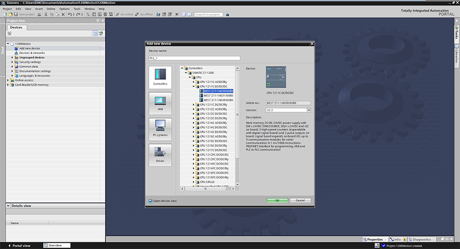
We’ll assume you have either a stepper motor or servo with a built-in encoder that can be actuated by controller pulses. First, add the PLC to the project.
Once added, go to Device configuration to do a standard setup, like setting the IP Address, and then enable the first pulse generator, PTO1/PWM1.
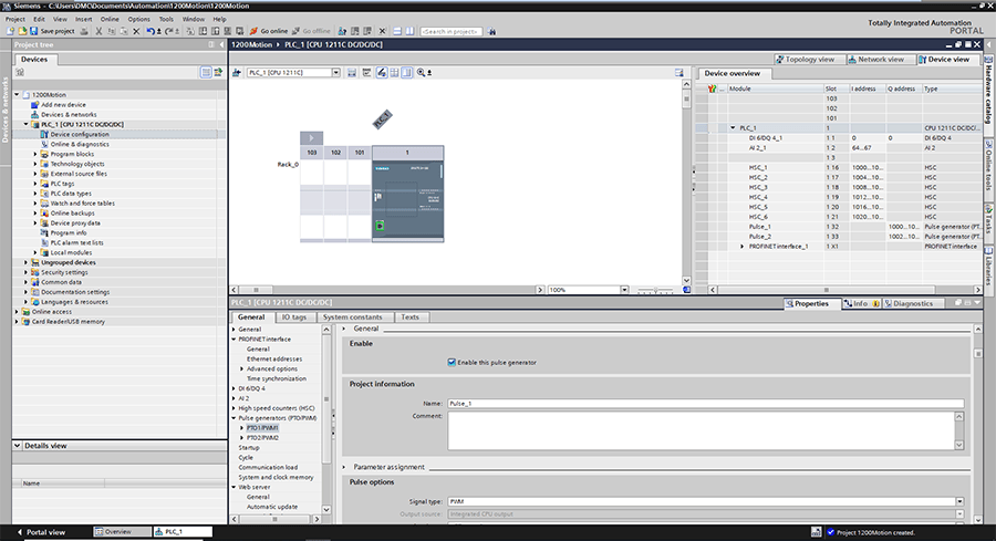
Be sure this pulse generator has the PTO signal type.
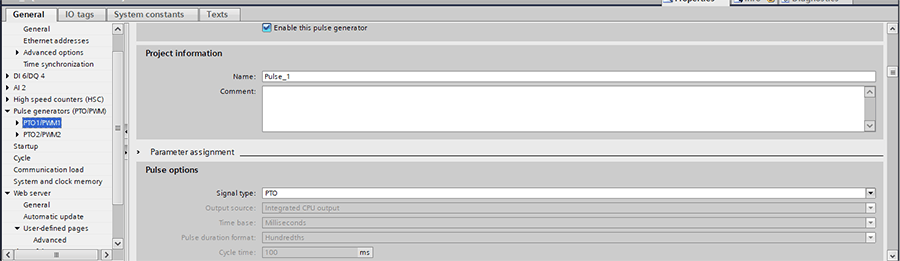
Note that the Pulse output will be at Q0.0, and the direction output will be located at Q0.1. We can then wire these to our motor.
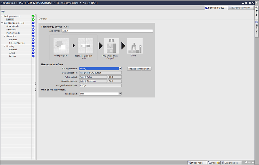
Next, we need to create a tech object. Click “Add new object” under the Technology objects folder, and then select “TO_AXIS_PTO.”
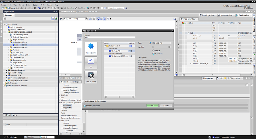
Next, when you create the text object, select “Pulse_1”. Also, be sure to choose the correct position unit; Here I’ve chosen degrees.
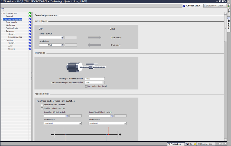
Finally, at a minimum, you should enter the pulses per motor revolution and the load movement per motor revolution into the extended parameters. This step will ensure that your commanded speeds and positions are correct.
If you are interested, now you have the full power of the technology object to go in much greater depth with your motion control configuration. For now, we want to get this done quickly, so we’ll leave it at the mechanics' parameters.
Now our tech object is configured, and we can program some motion. We can now build up a lot of complicated ladder logic, but if all we want is to make the drive spin, we only need two blocks: MC_Power to enable it, and MC_MoveVelocity to get it moving.
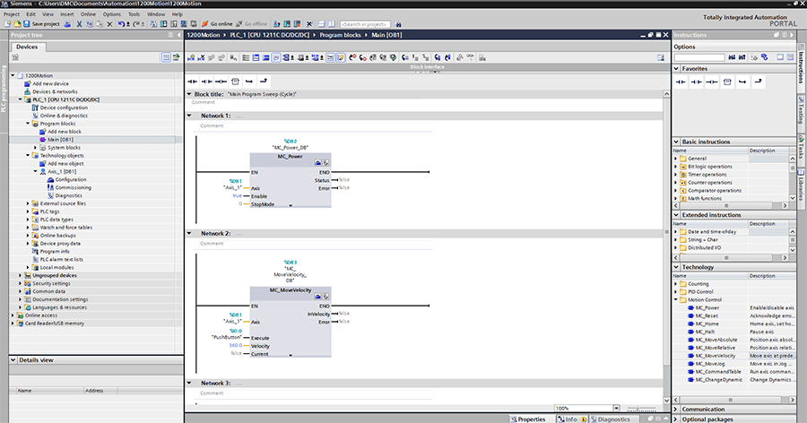
Here, for the “Axis” inputs, I entered the Technology object. I put a “true” in the enable input for MC_Power for it to always be on, set the Velocity to 360.0 degrees per second (60 RPM), and then wired up a pushbutton from the first PLC digital input to the execute demand. I can now download the project to the PLC, press the button, and have a spinning motor!
Of course, in a real production setting, you’d want to have the ability to reset the drive if there is a fault, make absolute and relative position moves, and probably want a more thought out and formal structure to your code.
I hope this example showed you how simple it is to get basic motion working on the S7-1200, so you can avoid headaches and spend more of your engineering effort on the specifics of your own use cases. There is quite a lot of cool stuff you can do with simple motion control. If you’d like help with any of your motion problems simple or complex, please feel free to contact DMC.
Learn more about our Motion Control expertise and PLC programming services.