Using MagneMotion track instead of a more traditional conveyor system allows for much more customization without sacrificing reliability. The magnet-powered conveyance system, developed by Rockwell Automation, provides a lot of flexibility when moving vehicles independently of each other and more direct control on how material moves down a line.
If you are trying to get started setting up a MagneMotion system, it can be hard to know where to start. Since DMC developed one of the largest and most complex Magnemotion systems in the world, we wanted to go through the steps to program and commission a complicated MagneMotion system. To get your MagneMotion system off the ground you will need to set up at least one node controller, commission its connection to your track and maybe create a complex PLC program to control your system.
MagneMotion Guide Series
Components of a MagneMotion track:
- One or more Node Controllers
- Several MagneMotion “motors” that are assembled into a track
- Host Controller (Typically a PLC)
Here, we will be working with a MagneMotion Lite system composed of ethernet motors, however, a lot of this information will still apply to Quickstick systems and RS-422 motors. We will also be using a Rockwell PLC so we can take advantage of Rockwell’s Independent Cart Technology library of reusable MagneMotion code.
The Configuration File
In this first blog, we will walk through how to create the configuration file for your system. This file is an XML file that tells your node controller(s) how the system’s track is laid out and any relevant information that they will need to know in order to control the system’s motors. Configuration files are typically made using the MagneMotion Configurator tool.
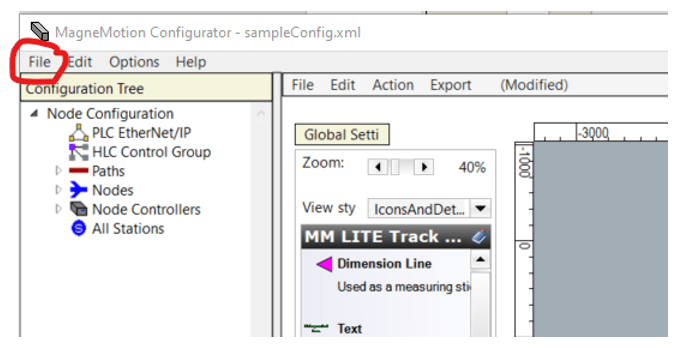
For this setup, we will be using the MagneMotion Configurator tool, which you can download here.
Step 1: Create the Track Layout
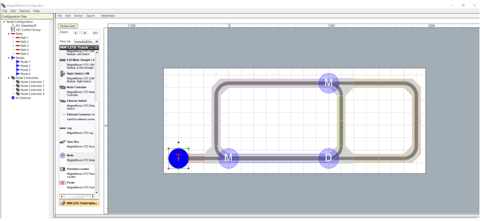
The first step is to create the track layout file. This can be easily done in the configurator. Drag each motor from the left-hand menu to create whatever track layout you have designed for your system.
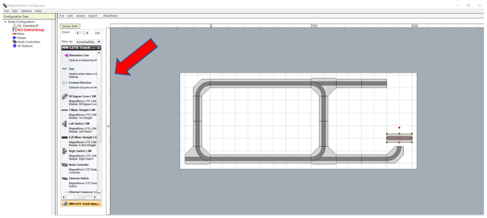
The motors usually snap together well, but you might have to use the right dot above the motors to rotate them into position before they can connect to the other motors.
Note: for Quickstick motor configuration, this graphical display is not available and tracks need to be created directly in an XML file.
Step 2: Place Nodes & Walk Paths
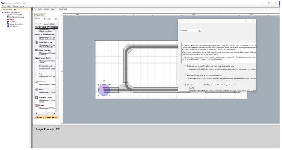
Once your track is complete, the next step is to manually place the first node of the track down. “Nodes” describe places where two paths of the track merge, diverge, or where one path of track ends/begins. Think of paths as a continuous chain of motors between two switches, and nodes as the points where one path ends and one or more paths begin.
In my track, pictured below, I’ve created a simple terminus node at the beginning of the track to signify that that is the point where the track ends.
Once you have your first node down, go to the top menu and select Export -> Place The Nodes. This fills in the rest of your track.
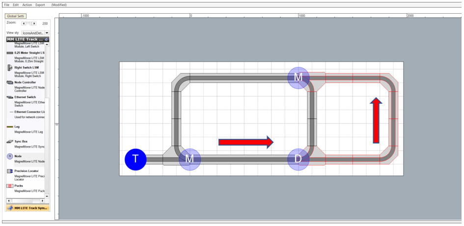
The “merge nodes” are places where two paths meet up in a switch and the “diverge nodes” are where one path splits up into two paths.
As it is configured now, the main direction of travel along the track will be counterclockwise around the loop. This is because the node placement started at the terminus node and therefore must travel in a counterclockwise direction to complete the entire track.
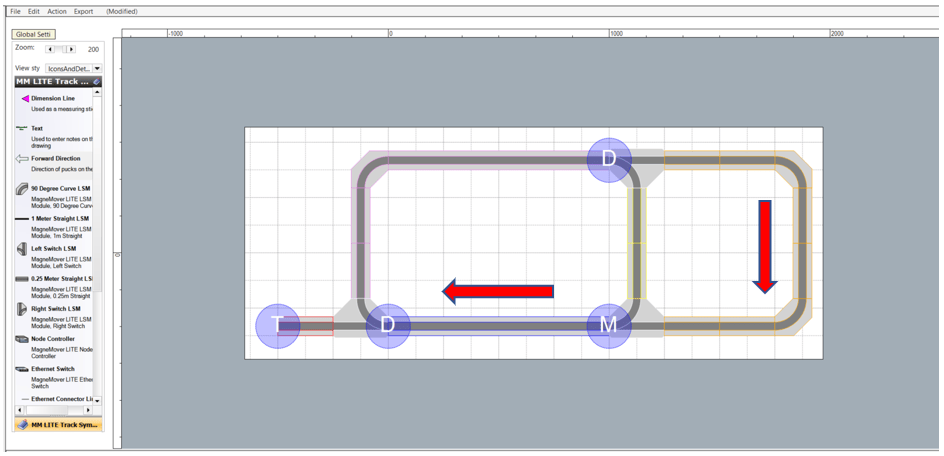
If I wanted to have the default track direction be clockwise, I can remove all of the nodes and place a diverge node where a merge node once was and vice-versa. Then when I place the nodes again, a slightly different node setup will be arranged with a clockwise default track direction instead of counter-clockwise.
Note: that vehicles can still be moved in either direction in each configuration.
After the nodes are placed, go back to the export tab and select “Walk the Paths.”
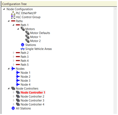
Now you can see that the track is divided into five paths between the four different nodes. You can also see in the left-hand tab under “Configuration View” that the configurator has started creating the path and node definitions for the configuration file.
Now is a good time to save the track file before we start modifying the configuration.
Step 3: General Configuration Settings
First, go to the very top of the configuration tree and select “Node Configuration.” This brings up a menu of various basic settings that apply to the whole system.
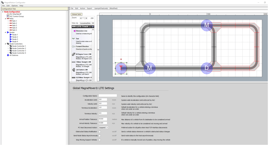
In this menu, there are values for the maximum allowable velocity and acceleration for your track, along with tolerances for your system. There is also an option for whether you want to have your system suspended if the controller of the system disconnects from the node controllers. Typically, leaving this on is recommended to ensure safety and best practice for your system. If this option is needed to be turned off, you can set it to “None” and have your system continue moving vehicles along the track even when the host controller is unavailable.
In the configuration tree, now select PLC EtherNet/IP to bring up another window of configuration settings.
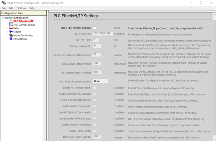
Here you can define your system as being controlled by a PLC. This option is typically only used when controlling your system with a Rockwell PLC and using Rockwell’s ICT library for handling PLC to node controller communication—which is the setup we will be using for this blog series.
With PLC control selected, make sure you check the parameters for the PLC IP address and that the “Max Vehicle ID” is at least as large as the maximum number of vehicles you might have in your system at a given time. There is also a “PLC Host Disconnect Action” option similar to the “PC Host Disconnect Action” discussed in the previous menu. Lastly, make sure that you enable traffic lights if you are planning to use them in your track.
Step 4: Modifying Configuration and Path Values
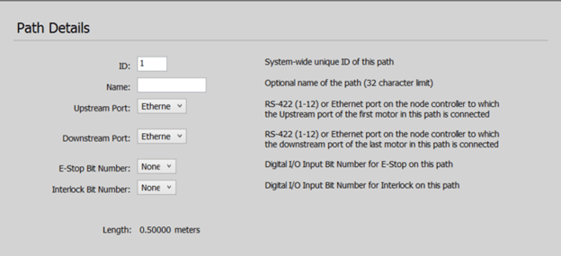
Once you verify that your general configuration values are appropriate for your system, select “Path1” in the configuration tree. Here, you can define whether or not you are using Ethernet motors and which port the RS-422 port is connected to. If you are using RS-422 ports, each RS-422 port assignment must be unique.
Expand path 1 and select “Motor Defaults.” Here you define path-specific parameters for the system.
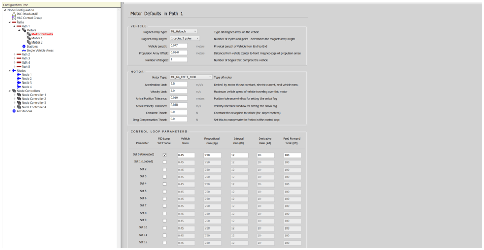
Make sure you define the vehicle length to be greater than the largest corner-to-corner distance of whatever will be positioned on the vehicle. This ensures that two vehicles never crash into each other while moving. It is also important to define the number of bogies. This value denotes how many MagneMotion pucks make up a single vehicle. Typically, this value will be one, but will need to be set to two if you are using tandem vehicles. If this value is incorrect, the paths of your system will refuse to start up. You cannot have a system that uses both tandem vehicles and non-tandem vehicles.
Verify that the vehicle mass is appropriate and if it will vary considerably (i.e., if a heavy weight is added or removed from the vehicle). Consider adding different PID settings that can be used to guide heavier or lighter vehicles.
Once you have a single path’s parameters, update the rest of the paths as well. If you have a large system with an extensive number of paths, you can save the configuration file and open it up as an XML file in a simple text editor, then perform a find and replace to update path values more rapidly.
False


			1

			Ethernet
			Ethernet


				ML_G4_ENET_1000
				2.0
				2.0
				0.010
				0.010
				0.0
				0.0


						0
						0.45
						750
						12
						10
						100


				ML_Halbach
				0.077
				3
				3
				0.024700
				0.0247
				1
Even if you choose the modify all the path settings in the configurator, it is still worth opening the XML file directly because there are some values that are not displayed in the configurator tool. For example, you can modify the Control_Loop_Control_Off_Distance parameter to keep motors from applying force to a vehicle if is within a certain distance from its destination.
Step 5: Assigning Node Controllers
Now that paths are sorted out, look at the node controllers section of the configuration tree. The configurator defaults to assuming each node is controlled by its own node controller, so you will have to delete node controllers until the number in the configuration tree matches the number in your physical system. Also, make sure you assign the IP address of each node controller.
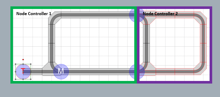
For my small track, I decided to split it into two node controllers. However, in a normal system this would be unnecessary as one ethernet-based NC is capable of handling 18-26 nodes. It’s important to note that RS-422 motors are limited by their number of ports, which can be as few as four.
The next step is to assign nodes to controllers. It is best practice to try to keep the nodes grouped in a way that limits how frequently a vehicle swaps between node controllers. I have decided to add nodes 1 and 2 to NC 1 and nodes 3 and 4 to NC 2. You can add and remove nodes by selecting their ID in the node ID dropdown and clicking either “Take Ownership” or “Remove Ownership.”
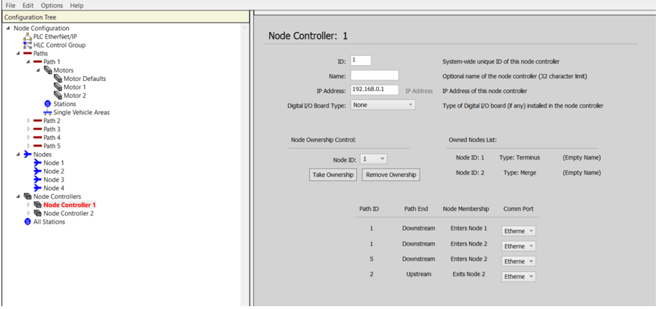
In this setup, NC 1 controls paths 1, 2, and 5, while NC 2 controls paths 3 and 4.
One of your node controllers will have to be designated as the high-level controller (HLC) of your track. This is not defined in the configuration file, but will need to be set later in the process.
Step 6: Generating MICS file
Along with a configuration file, each system needs a MagneMotion Information and Configuration Service or MICS file. The purpose of the MICS file is to tell the node controller how to connect to each motor in the track layout.
A MICS file is a simple XML file with a single entry for each motor. This includes the motor’s MAC address, desired IP address, path and motor number, and orientation.
Below is an example MICS file for a system that contains only three motors:
        C0:6C:6D:03:19:EF
        10.127.129.0
        P1M1
        Standard


        C0:6C:6D:03:1A:FA
        10.127.129.1
        P1M2
        Standard


        C0:6C:6D:03:1D:56
        10.127.129.2
        P1M3
        P2M1
        Standard
Did you notice how the third motor has two track location entries? This is because that motor is a switch, so it is the third motor on Path 1, while also being the first motor on Path 2. Every switch in the system must be assigned two track locations since they are, by design, always a part of two separate paths.
Note: all left curves need to have their orientation set to reverse in the MICS file.
Once you have defined all your motors in your MICS file, you will be ready to start commissioning your node controllers.
Step 7 (Optional):
Now that your configuration file is set up, you can use the MagneMotion Configurator Tool to create a track layout file that will be useful later when commissioning your system.
With your configuration file open in the configurator, go to File -> “Create Track File from Config,” name, and save your track file somewhere convenient.
Topics to look forward to in this series:
Read more about DMC's manufacturing and automation intelligence expertise and contact us today to get started on your next project.