In the last blog (MagneMotion Blog Part 5: Advanced Vehicle Controls) we discussed using additional PLC commands to send vehicles around a track. Here we’ll discuss general strategy for reinitializing and startup up your MagneMotion system.
MagneMotion Guide Series
Track Recovery Overview
One of the difficulties of managing a MagneMotion system is learning how to properly startup the track and get things running. Whether you’re starting up the track for the first time or recovering after a major fault or a power cycle, there is a single sequence you should take your system through to get everything operational again.
Here is a short list of the various reasons you might need to re-startup your MagneMotion track:
• There was a power cycler of motors or node controllers
• A communication/network issue between the node controllers and the motors
• A communication fault between the node controllers and the PLC
• Motor faults that stop movement on the track
• Vehicles have been pushed out of position and are now “suspect”
• Configuration file changes
While all these issues have potentially different resolutions, it is generally preferred to take care of all of these issues in a single startup sequence to make sure that all edge cases are handled on recovery and to make the operator interaction of the line as easy as possible.
In this article, we’ll look into each of the steps this sequence has to take to fully recover the track and what each step does for the overall MagneMotion system.
Step 1: Reinitialization
Among the list of useful ICT library AOIs is the Device Status AOI. This AOI is mainly used to check on the current status of the MagneMotion system and its connection to the PLC.
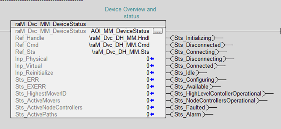
When you’re recovering your MagneMotion track, the first thing that should be done is triggering the Inp_Reinitialize bit of the Device Status AOI. This will cause the PLC to get rid of the current connection to the High Level Node Controller (HLC) ensuring that whatever you do next will be happening from a clean slae.
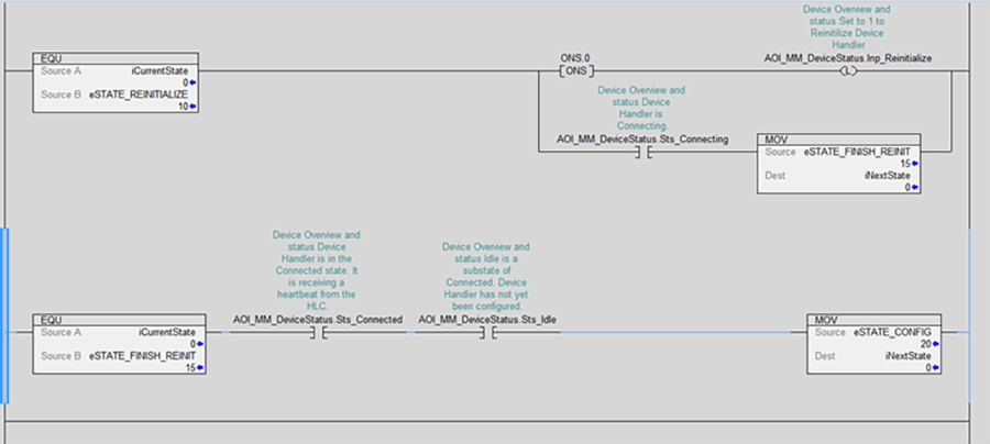
After triggering the reinitialize bit you should check the connection statuses from the Device Status AOI. Once the AOI is back to being Connected and Idle the reinitialization process is complete.
Step 2: Configuration
The next step in our sequence is to use the Configuration AOI to re-configure the PLC to HLC communication. (Learn more about the Configuration AOI in MagneMotion Guide Part 3: Controlling a System with a PLC)
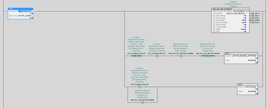
Using the Configuration AOI will direct the PLC to connect to the right IP address for the System’s High Level Controller. This step help to ensure that the PLC and HLC are communicating properly. If there is an issue with the communication, the Configure AOI should throw a fault to indicate its inability to connect. Once this instruction completes the sequence can proceed to the next step.
Step 3: Disable Stations
Typically, MagneMotion systems controlled by a PLC will have several Stations created to help control where vehicles are sent to. (Learn more about stations in MagneMotion Guide Part 4: Using Path and Station AOI’s)
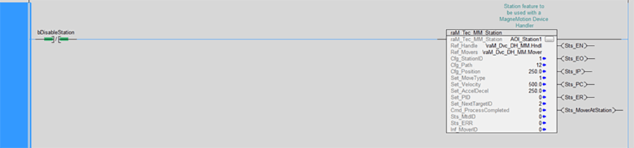
If at any point a station encounters a problem it will throw an error and stop working until that error is cleared. This means that any vehicles directed to this station will remain stationary on the track and any vehicles at this station will be stuck. Typically, this happens when a vehicle that cannot reach a station is told to move there.
To clear station errors the Station AOI needs to temporarily stop receiving calls, so in this step we disable the station call.

Step 4: Reset Paths
If there have been any sort of errors with MagneMotion motors or with vehicles on the track, the paths of the system will need to be reset using the Path AOI (Learn more about paths in MagneMotion Guide Part 4: Using Path and Station AOI’s)
Resetting the paths will cause the MagneMotion system to lose track of which vehicles are where. If in your system you do any sort of internal tracking of what is on each vehicle, you will want to clear that information out before resetting paths so that your PLC will not have outdated/incorrect information about the contents of each vehicle.
This is generally the most important step in the Startup Sequence. At this point any track issues should be resolved, all that is left is to finish starting the track back up and get vehicles moving again.
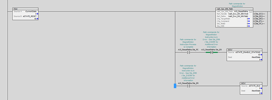
Step 5: Enable Stations
Now that paths are reset it is safe to re-enable stations. If stations are re-enabled before the resetting step any ongoing faults in the track could re-trigger the station faults requiring them to be disabled again before they can be operational.
For example, if a station was faulted by a vehicle being improperly directed to it, that station fault will not be able to be cleared until the paths have been reset removing that vehicle from the track.

This will allow the station AOIs to be called again, clearing any errors they had and allowing them to operate normally again.
Step 6: Startup the Track
This step is a complement to the previous one. Here we send a startup command to all the paths in the system which will make the track operational again and assign vehicle IDs to everything on the track.
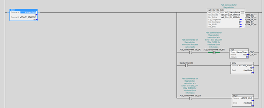
Every once in a while, the Startup AOI will briefly set the STS_PC output to indicate that it is done before it sets the STS_ER output to indicate that a path has faulted. To make sure everything is properly started up, I usually like to add in a brief delay before proceeding to the next step.
Step 7: Vehicle Homing
Now that the track has been successfully started up, the next step is to tell all of the vehicles on your track where to go. There are several different ways to do this, and each system will have different requirements about what needs to happen to vehicles on a startup. I typically like to go with sending every vehicle to a single startup location that then decides where each vehicle can go as they show up.

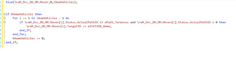
In the above example we simply iterate through the Mover array from the ICT Library programs and direct each vehicle to a defined station. We also have a quick check to make sure that vehicles on one particular path (which can’t reach the home station) are not directed to the home station.
For your system you can also fairly easily decide to direct vehicles to different locations based on their location on startup with some additional checks to vehicle position before you set their target station ID.
Step 8: Data Tracking Recovery
So far, the startup sequence works for a system that doesn’t require tracking the information on vehicles, or a system that would clear vehicle contents out before the track has started up. But what should you do if you want your system to remember what is on each vehicle even after a complete restart of the track?
Since MagneMotion itself loses track of which vehicle is which during startup there is no direct way to correlate old tracked vehicle data to whichever new vehicle IDs MagneMotion produces on startup.
One way to solve this problem would be to develop a complicated vehicle tracking program to try and determine what vehicle contents belong to which vehicle after a startup based on the positioning of the vehicle before and after a full startup of the track. Putting aside the considerable complexity of this plan, there are several added complications where vehicles can be moved while the system is powered down and can drift after power loss in ways that could quickly make any recovery logic very hairy and unreliable.
Another more robust solution to this problem is to affix a unique barcode to each MagneMotion vehicle. Then once the system is reset you can direct each vehicle to a barcode scanner positioned near the track that will scan each vehicle and report to the PLC what its barcode is. Then with this barcode you can create a more robust system for assigning tracked vehicle contents with MagneMotion vehicle IDs.
Additional Considerations
While the above sequence is generally sufficient in restoring a MagneMotion track, there are some important additional things to take into account when commissioning a MagneMotion system.
1. Some rare MagneMotion faults might require a full reboot or power cycle of the Node Controllers of the system. This is not done through PLC commands but is typically done manually through the Node Controller web page.
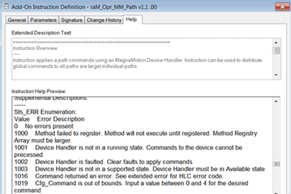
2. Each MagneMotion AOI has its own error code and extended error code output (STS_ER and STS_EXERR). Documentation for these error codes can be found in the help files for the ICT library or in the help section of the AOI properties.
3.. Additional Error information can be found in the log files of the node controllers, but these error codes are often fairly difficult to read.
4. If you are building a system that attempts to recover vehicle information after a restart, it is generally useful to include an alternative startup that will default to assuming that every vehicle is empty.
5. If your system involves vehicles travelling at different speeds based on their contents, remember to lower the speeds of all vehicles until the system can determine what is on the vehicle.
6. If your system has traffic lights, they will be deleted every time the paths of your system reset.
Topics to look forward to in this series:
Learn more about DMC's MagneMotion expertise and contact us to get started on your next project.