In our previous blog (MagneMotion Blog Part 7: Traffic Lights) we discussed how to best make use of MagneMotion’s traffic light feature to control the flow of vehicles around your track. In this blog, we’ll discuss how to simulate a MagneMotion track.
Simulation can be a powerful tool for testing things out on your system, especially if you’re waiting on long lead time hardware to actually commission your system. Fortunately, MagneMotion has a very simple Simulation setup that works very reliably.
MagneMotion Guide Series
Requirements
To simulate a MagneMotion track, you will need a physical Node Controller that will run the actual simulation. Even if your system will need multiple Node Controllers, you typically only need a single Node Controller to run that track in simulation mode as long as your entire track can fit on a single High Level Control group.
While you can get some value out of a simulation of just a Node Controller and an NC Host, you will also likely want to have a physical PLC to run your controls software on so that you can more fully test out your routing logic.
For the purposes of this blog, we’ll assume you already have a configuration file for your Node Controller (MagneMotion Guide Part 1: Creating Configuration Files) and a PLC project to use for simulation (MagneMotion Guide Part 3: Controlling a System with a PLC).
Updating the Configuration Files
The first step in simulating your track is to update your configuration file to include simulated vehicles.
If you cannot see the simulated vehicles under the Paths of your system, go to Options > Show Simulated Vehicles to display them.
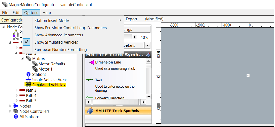
Now, open whichever path you want to place your simulated vehicles on, right click on Simulated Vehicles, and select “Add To End.” This will create a simulated vehicle that will appear on that path on startup in the specified location.
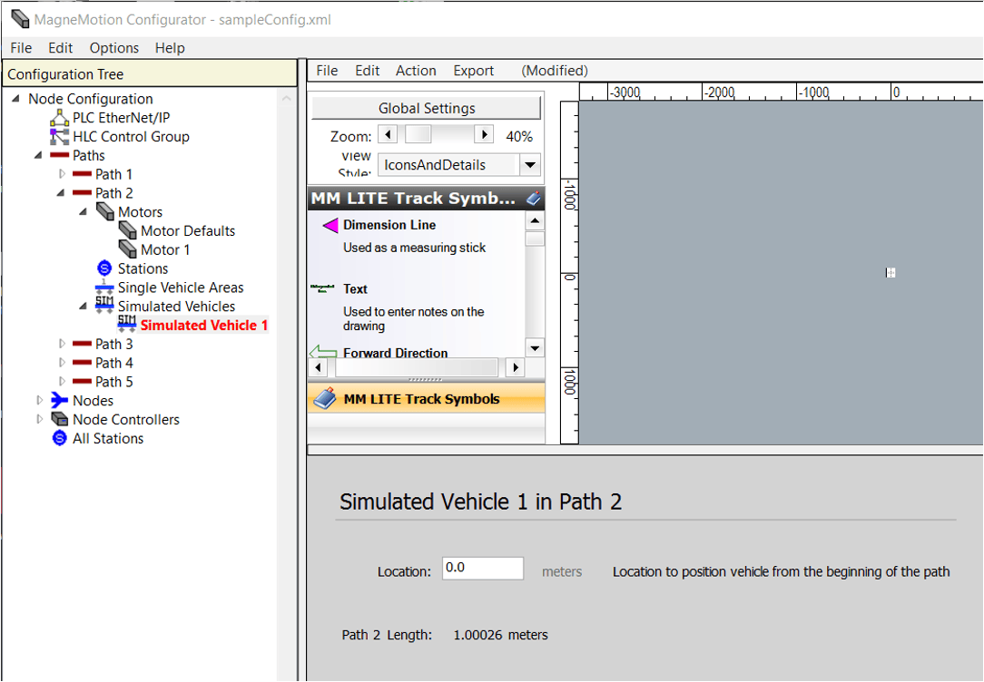
Repeat the above steps to create as many vehicles as you want for your simulation. Make sure to separate the vehicle locations so that they are not all in the same spot, and do not add more vehicles than what can fit on the path.
Simulate the Node Controller
Now that you have an updated configuration file, go to the Node Controller web page and upload the new configuration file.
Once that is done, go to the IP Settings page of the Node Controller and check the box that says “This box is a High Level Controller Simulator” under Configured Functions. Make sure that the other two boxes are unchecked.
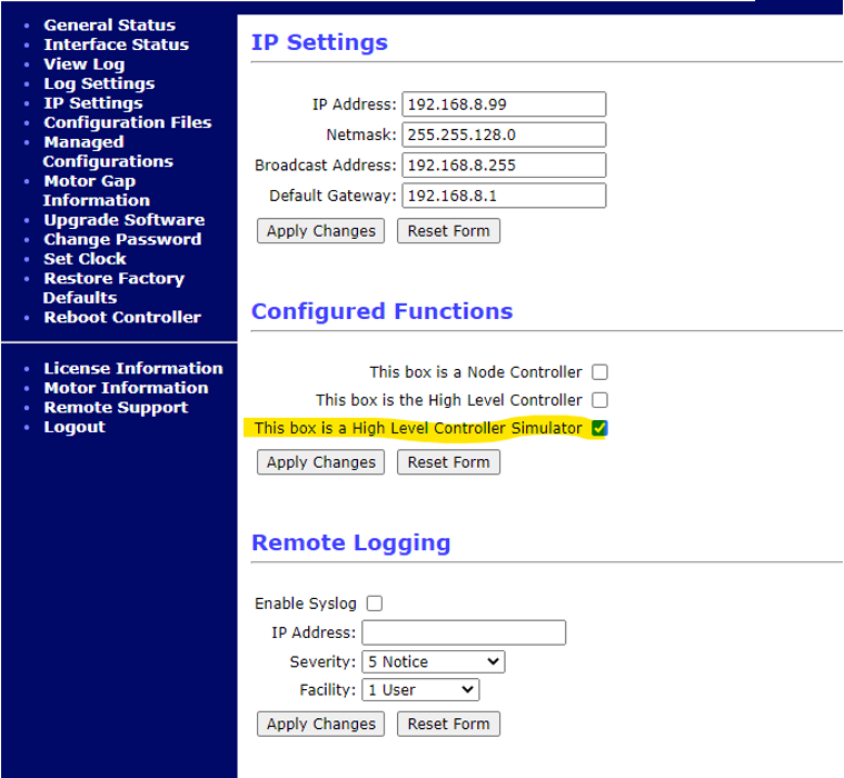
Next, hit the Apply Changes button and reboot the Node Controller. When that is done, you should be all set to run your simulation.
To verify that it worked, openNC Host (MagneMotion Guide Part 2: Starting up and Commissioning a Track), attempt to reset, and then startup the paths on your simulated Node Controller. If everything is working properly, you should be able to see the simulated vehicles you added to the configuration file.
PLC Simulation
There should not be a need for PLC code changes to get your PLC to work with a simulated Node Controller. As far as the PLC is concerned, a simulated Node Controller and a Node Controller running an actual line of MagneMotion track are the same thing. The logic for connecting to the controller, sending commands to it, and interpreting messages from it should all be the same in a simulated environment.
This does not mean it is impossible for new issues to arise once the PLC program is moved to work with a non-simulated Node Controller, however. The time it takes the Controller to run various instructions will be different in a simulated Controller, so watch out for race conditions.
It is also entirely possible that the Node Controller will pass back slightly different messages to the PLC while it is being simulated, and there are numerous errors and fault conditions that can only appear when using actual MagneMotion track that a simulation will not catch.
Simulation Tips
While you are simulating your system, there are several important things to keep in mind.
First, always remember that — while the MagneMotion simulation does a great job simulating routing vehicles along a representation of your track — there will always be additional considerations with a physical system. Any physical considerations like vehicle nest collisions, unbalanced vehicles, or devices interacting with the MagneMotion track will not be accounted for in the Simulation.
Second, it is also important to attempt to simulate a variety of conditions in your system. Typically, the easiest way to do this is to regularly modify your configuration file to have different amounts of vehicles and change where vehicles are positioned on the track, but additional variety should be added by manually redirecting vehicles around the track to ensure that all the routing edge conditions are checked.
A physical environment is much less predictable than a simulated environment, so it is important to make sure that the routing software is not only tested for a single, ideal set of conditions.
Positive Things to Verify Through Simulation
- Station Layout
Having your track simulated is a good opportunity to verify your overall track layout. While you cannot fully verify that your track layout is ok in simulation, you can make sure that the Node Controller is able to send vehicles from point A to point B without issue. This will allow you to catch various errors that can stem from configuration file issues
- General PLC and Node Controller communication
Since the Node Controller communicates to the PLC in the same way, regardless of whether it is a simulated controller, simulation offers a great chance to test PLC communications. The configured connection to the Node Controller, along with all of the array lengths used in the MMI tags passed between the Controller and the PLC, can all be verified in simulation
- Routing Logic
The main thing to test in any track simulation is whether the PLC logic works. All logic surrounding whether the PLC is telling which vehicles to move, the location to which they should move, and at what time, can typically be very robustly simulated.
This is a great chance to test if vehicles are being told to go to the right stations and to verify that the PLC is appropriately tracking any information associated with each vehicle. Keep in mind that there will potentially be some differences with the various reactions the Node Controller has to PLC commands that could affect the functionality of the PLC logic.
- Traffic Light Operation
Traffic lights can be fairly reliably simulated; however, keep in mind that, since the timing of Node Controller actions will vary between a simulated controller and running actual track, any time sensitive traffic light operations cannot be tested (ex. if you want to set a traffic light red before a vehicle gets to the end of a path, you would not be able to properly test the timing of the traffic light in simulation.)
Also, keep in mind that the ICT library blocks for handling traffic lights are relatively new, so they are liable to have fault messages pop up when running on an actual track that might not show up during simulation.
- System Throughput Estimations
While simulation is not suited for calculating exact throughput calculations, it can be a very useful way to get a rough benchmark of your system’s throughput. It is fairly easy to modify your PLC code to use a variety of timers to test how quickly your system can run and to see how long it will take vehicles to cross your track.
- Traffic Jam Analysis
Simulation can also be a valuable tool for testing whether your system has any concerning traffic jams that might need to be addressed. Simulation is a great time to answer questions like: Does sending too many vehicles to Station A block off Station B? If vehicles leave Stations C and D at similar times, do they get in each other’s way?
By varying the number of simulated vehicles on your track and the starting locations of those vehicles, you can robustly test routing vehicles across your system to get an early diagnosis of any lingering traffic considerations.
Negative Things to Verify Through Simulation
- Vehicle spacing and collision avoidance
Theoretically, the vehicle length set in the MagneMotion configuration file will prevent any vehicle collisions, but, in practice, it is always a good idea to thoroughly verify that vehicles placed close to each other will not collide when going through switches or when going around hairpin turns. Take special care if your vehicles are notably wider than the MagneMotion pucks.
It is likely you will also need to fine-tune the positions of many of the stations and traffic lights of your system; while a first pass of this can be done in simulation, the final values for these positions should be set during the commissioning of the physical track.
- Track Startup
The general function of any startup logic can be tested in simulation (configuring MM communication, resetting paths, creating traffic lights, etc.); however, since one of the main purposes of startup logic is to recover from faults, it is very difficult to verify that it recovers from issues. This is because simulated tracks will always start from an ideal clean slate.
Feel free to run some tests on startup logic for simulation, but do not assume a startup sequence that works in simulation will also work with a physical track.
- Station Positions
Since station positions are generally affected by physical factors like robot arms, device positions, or Operator preference, it is generally best to hold off on fine-tuning station positions until you are working on the physical tracks.
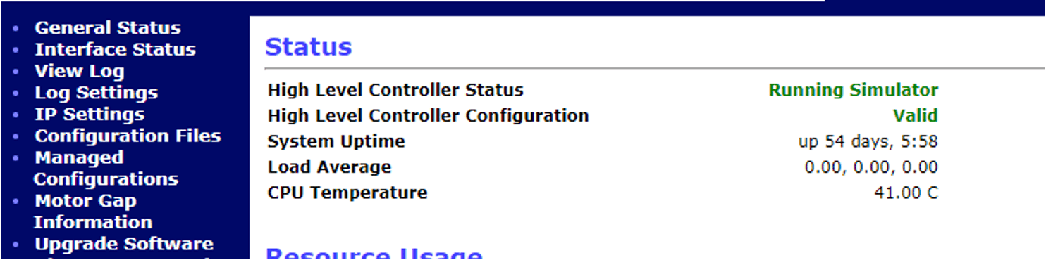
- Node Controller Load
In the General Status page of the Node Controller webpage, there is a value for the load average of the Node Controller. These values should always be less than 1 (ideally less than 0.8). If the values for this get too high, it is an indication that your Node Controller is overloaded. Simulation will typically have very low Load Averages, but this is not an indication that the actual implementation of the track will have similarly low load averages.
- Networking
Since a simulated Node Controller will not be networked to the various MagneMotion motors, do not assume that the PLC and the Node Controller networking is fully functional from simulated tests alone.
- MICS File
Simulation testing will not verify whether the MICs file has the correct MAC addresses or the correct orientations for motors.
- Terminus Node Handling
There have been issues simulating Terminus Nodes and having vehicles enter and leave through them. While there have been some recent MagneMotion firmware updates that should improve this issue, you should still be extra careful when testing Terminus Node behavior after simulation.
Topics to look forward to in this series:
Learn more about DMC's MagneMotion expertise and contact us to get started on your next project.