A central part of each MagneMotion system is the node controller. This device is what controls the motors of your track. Even if you are using a PLC or computer to control the overall system, the node controller will send commands to your motors and coordinate how a vehicle will be moved across a track.
Assuming you already have your Configuration and MICS File, the next step is to program your node controllers and motors to finish the initial setup of your MagneMotion System.
(If you do not have a Configuration or MICS File, see MagneMotion Guide Part 1:
Creating Configuration Files.)
MagneMotion Guide Series
Step 1: Using the Node Controller Webpage
To properly set up a node controller, you will need to access that controller’s webpage. To bring up the controller’s webpage, simply type the controller’s IP address into a web browser while you are connected to it. (For a new node controller, the default IP address is 192.168.0.1.) When you first pull up the webpage, you will get a prompt to log in to the page using a username and password.
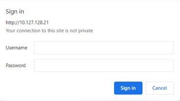
(Default username/password is admin/admin)
Once you are on the webpage, navigate to the IP Settings page.
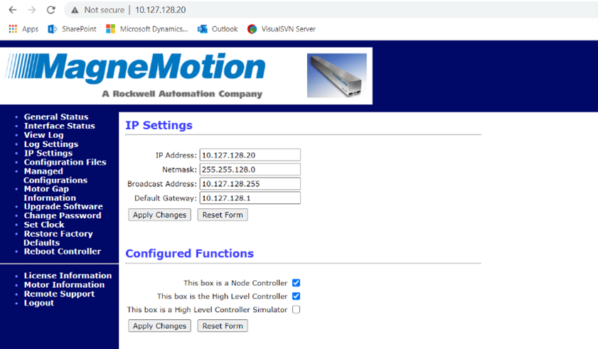
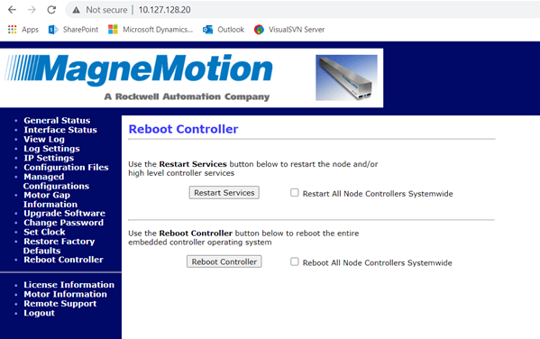
From here you can set the IP address setting of the node controller. Once you are done, hit Apply Changes. Then go to Reboot Controller in the left-hand menu and restart services on the node controller.
Now, if you have changed the controller's IP address, you will have to navigate to the new address to continue accessing the web page.
After the page reloads under Configure Functions, check the box for “This box is a Node Controller,” and, if the node controller is going to be the High Level Controller (HLC) for the system, make sure that box is checked as well and then Apply Changes and restart services again.
(If a system has multiple node controllers then one of those controllers is selected to be the HLC of the system. If there is only one node controller, that will still need to be set as an HLC.)
Now, repeat this process for every node controller in your system—making sure only one of them is set as an HLC.
Step 2: Uploading Files
Once the Controllers are set up, it is time to upload all of the necessary files. Go to the webpage of the HLC and go to the Configuration Files page.
Under Upload Node Configuration File, press Choose File, select the Configuration File you want to program the controller with, and then press Upload File. If you are using multiple node controllers, you can then press Distribute To All Node Controllers to upload the same file to them. Once the file has been uploaded, restart services for the node controllers to make the change take effect.
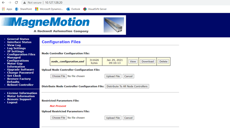
After uploading the Configuration File, repeat the process with your MICS File.
Note: MICS Files are only needed for ethernet motor tracks.
Next, you will have to upload Motor Type and Magnet Array Files. These files are not created by the user but are files created by MagneMotion to help define the hardware being controlled.
These files can be found here.
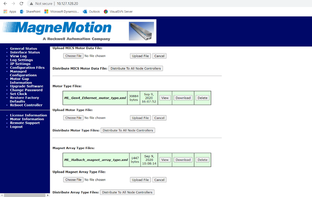
You will also need to navigate to the Upgrade Software page and upload ERF Files for the motors. These files are specific to the types of motors and are used to program the motors of the system.
ERF Files are also found here.
Once the files are uploaded and services have been restarted on the NC, go to the General Status page and verify that the Node Controller Status and Configuration are valid.
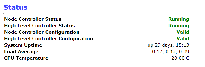
If any of the above statuses is not Running or Valid, navigate to the View Log page and resolve any error messages you see there. If it is the HLC Configuration and it is invalid, make sure that you are viewing the View HLC Log.
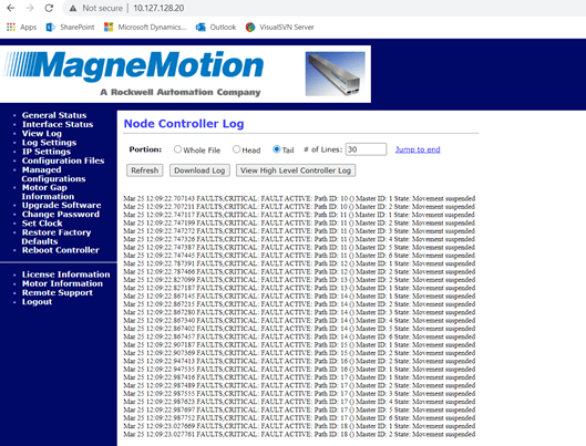
Typically, if the issue is with the HLC configuration, then there is an issue with the Configuration File that needs to be corrected. The log file should point you to which value in the Configuration File is causing the problem.
Note: it often points at a specific line of code in the XML File, so you will want to open the Configuration File up with a text editor instead of using the Configurator Tool.
When the issue is with the node controller Configuration, it usually involves some sort of Configuration File/MICS File mismatch. Common issues include when motors are left out of the MICS File or are not properly established as a switch in the MICS File. The log file should point you to which motor/path is the issue.
Step 3: Programming Motors
Once all of the necessary files are uploaded, it is now time to start programming your system’s motors.
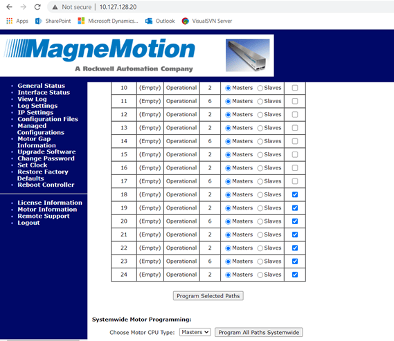
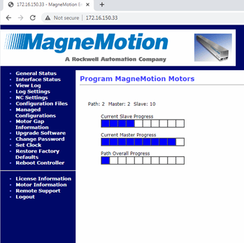
On the Upgrade Software page, scroll down to the Program Motors section. Here you can select which of that node controller’s paths you will want to program. Make sure that Masters is selected for each one and press Program Selected Paths.
Once paths have started programming, you will see the webpage display a status bar for each path as it is completed. This process often takes a few minutes, and, if there are any issues with the motors, a path will display an error message saying the path failed to program.
When troubleshooting why one path will not program, there are a few important things to check.
- Verify the connections to the motor. Typically, motor ethernet and power connections are daisy-chained from one motor to the next. If everything connects downstream and one motor refuses to program, you are likely to have a wiring or connectivity issue. You can also try pinging the IP address of the motor (that you assign in the MICS File) to verify that it is connected. Not being able to ping the motor does not necessarily mean that it is not wired correctly Since motors are assigned IP addresses through the MICS File a MICS File error will cause a motor to have no valid IP address.
- Power cycle motors. By default, MagneMotion motors will be trying to get IP addresses from the node controller, however, if the motor has been on for a while without being assigned an IP address, it will poll for a new one less and less frequently. Power cycling this motor will make it easier for the controller to assign it an IP address.
- Verify Configuration settings. Check that a motor’s MAC address and IP address in the MICS File are correct and that the motor defined in the Configuration File is the same type as the motor you are trying to program.
- Try programming the motors again. While it is not a very satisfying solution, these motors can be a little finicky so, when they refuse to program, sometimes the best answer is to start programming the motors again and pray to the Magnet God that it works this time.
Once all of the motors have been programmed, open NC Host.
NC Host is a tool provided by MagneMotion for controlling MagneMotion systems.
The install files for NC Host can be found here.
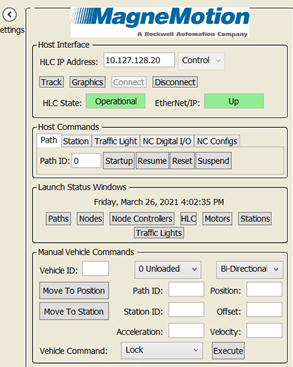
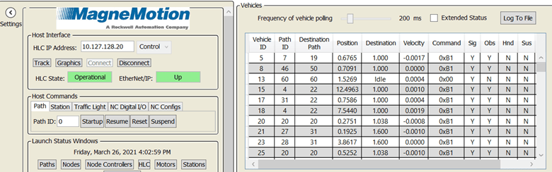
In NC Host connect to the system by typing in the HLC’s IP address and setting it to Control. Then press Connect to establish HLC communication.
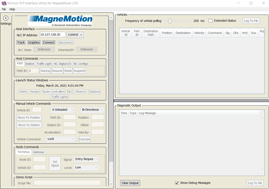
Once connected, reset the paths of the system from NC Host by having the Path ID under Host Commands set to 0 and pressing Reset. While paths are resetting, you can view their status by pressing Paths under Launch Status Windows.
After paths have been reset, go back to the webpage and restart services for all node controllers. Once that is done, repeat Step 3 while making sure to select the option to program slave motors instead of master motors in the upgrade software page. Since master motors were successfully programmed, slave motor programming should go fairly smoothly.
Note: it is possible to have a situation where a motor is configured to be the wrong type (e.g., a one meter motor is set as a .25 meter motor) and Master Motors can still be programmed but Slave motors cannot.
Once slave motors have been programmed, restart services on the node controller and reset the system paths through the NC Host again. When that is done, all your motors have been successfully programmed!
Step 4: Verifying Vehicles Can Move
With the node controller properly configured and all of the motors programmed, you should be good to start up the MagneMotion system.
Startup all the paths by making sure 0 is selected for Path ID under Host Commands and pressing the Startup Button. You can verify which paths have started up through the Path Status Display.
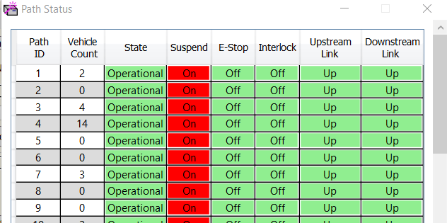
If a path will not start up, verify that none of the vehicles on the path are obstructed and that they are not all bunched together either.
While paths are started up, you will be able to see the status of all vehicles on the track in the status screen to the right.
To make a vehicle move, in the Manual Vehicle Commands section of NC host, fill out the fields by entering a vehicle ID and Path ID. You will also need to set the Acceleration and Velocity to non-zero values as well as set the position on the path you want to move the vehicle. (Acceleration is in m/s^2, Velocity is in m/s, and Position is in meters from the start of the path.)
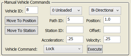
Make sure Bi-Directional is selected and click Move To Position. Assuming there is nothing in the way, you should see your vehicle move to the specified position!
Step 5: Using Track Files in NC Host
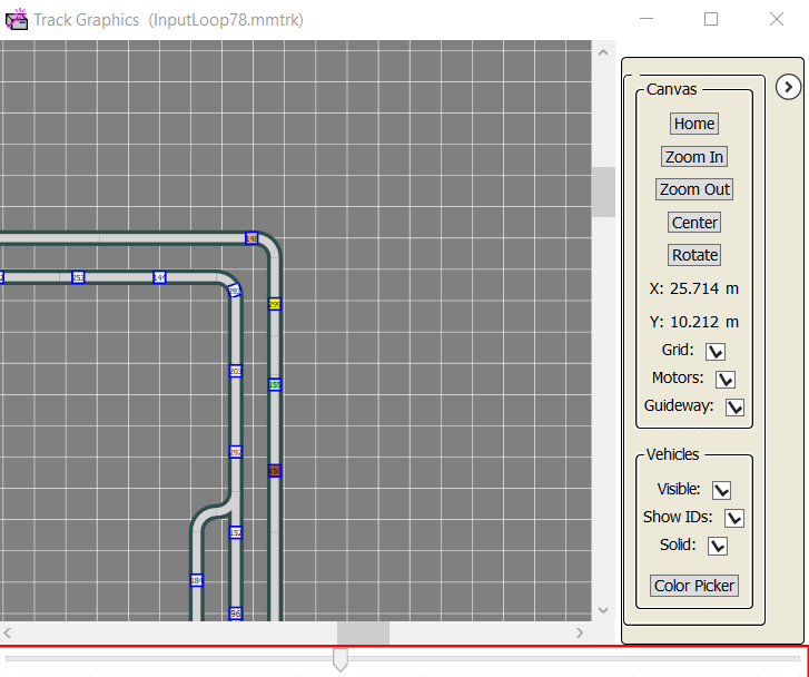
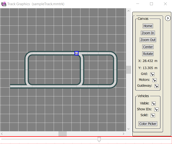
Another incredibly useful thing to do with NC Host is to create a visualization of the vehicles on the track.
In the MagneMotion configurator tool, open your Configuration File and go to File -> Create Track File from Config. Save the resultant mmtrk file and pull up NC Host.
Note: this cannot be done for disjointed tracks that are made up of two or more non-connecting track segments; however, for disjointed tracks, you can temporarily break out your Configuration File to create tracks so that you have a separate file for each disjointed segment. Now, you will still be able to run these checks with just a little extra effort.
In NC Host, press the Track button and select your mmtrk file in the window that pops up. Next, press the Graphics button to pull up an image of your configured track.
You should now see your track with any vehicles on it represented as little colored boxes on the track.
If you are looking at the graphic of your track file and wondering why it does not seem to match up with what you have configured, there are likely several small errors in your Configuration File.
For example, here is the track layout I created in the previous blog entry versus the actual Configuration:
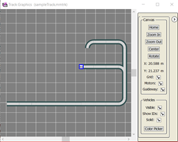
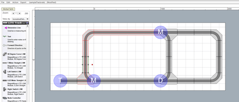
As you can see, my track file does not represent the actual Configuration of my system, so what went wrong? Usually, the issue involves a switch or curve is represented slightly incorrectly in the Configuration File.
In the above example, it turns out that the switch at the beginning of path three was correctly defined as a switch, but the Configuration File claimed that path three contained the straight segment of the switch and not the curved segment.
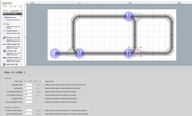
If I change the motor type from ML_G4_ENET_SWITCH_250_LEFT to ML_G4_ENET_SWITCH_CURVE_LEFT, then we get the right track layout.
Not only is the Track Graphics tool very useful for monitoring the vehicles of your track, but you can see it is also a handy way to verify that your track Configuration is sorted out.
Now that your node controllers and motors have successfully been set up, you should now be able to work on establishing the control system for your track.
Topics to look forward to in this series:
Read more about DMC's manufacturing and automation intelligence expertise and contact us today to get started on your next project.