In our previous blog, we covered how to set up a Node Controller to be controlled by a Rockwell PLC using Rockwell’s ICT library. Now that your PLC and Node Controller are set up, we’re going to cover using the Path and Station AOIs from the ICT library to control your system. You can find the ICT Library here.For either of these AOIs to function properly, make sure that your PLC to Node Controller communication is properly set up and configured.
MagneMotion Guide Series
Step 1: Using the Path AOI
One of the backbones of the ICT library structure is the Path AOI. This AOI allows you to command paths from the PLC in a similar manner to the way paths can be controlled from NC Host (For details on how to use NC Host see MagneMotion Guide Part 2: Starting up and Commissioning a Track).
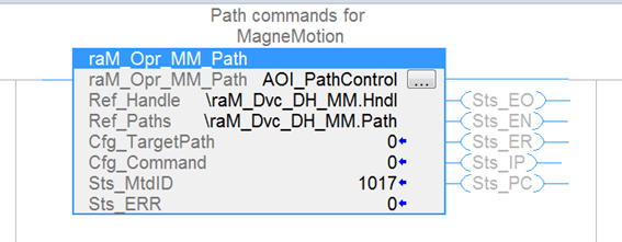
To setup the AOI, make sure that the Ref_Handle input is set to \raM_Dvc_DH_MM.Hndl and that Ref_Paths is set to \raM_Dvc_DH_MM.Hndl .\raM_Dvc_DH_MM.Hndl is a reference to the main ICT device handler task we generated in the last blog. If you have re-named your task, be sure to use that name instead.
Set the Cfg_TargetPath input to the path you want to send a command to. If you would like to command every path at once, leave Cfg_TargetPath as 0.
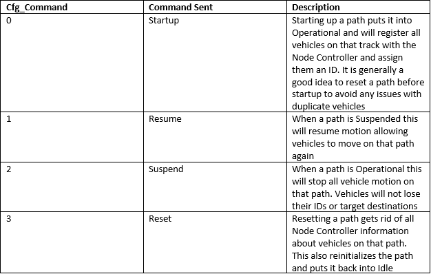
Cfg_Command will be different depending on which command you want to send to the Path:
In the example below, once bCmdPath is triggered the Path AOI will begin sending a command to the Node Controller. You will see the Sts_IP output of the AOI turn true while the command is being executed by the Node Controller. You can watch the path status change in NC Host to follow along. When the command is done you will either see the Sts_PC bit turn on, indicating that the command is done, or you will see the Sts_ER bit to indicate that there was an issue completing the command.
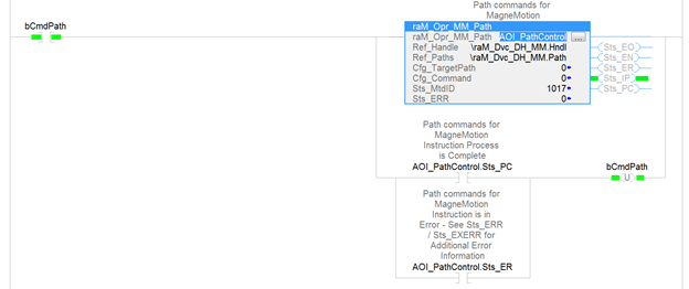
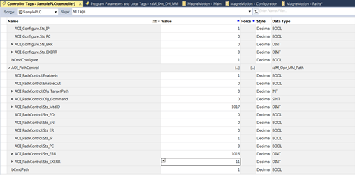
If the command fails and an Error code is returned, look at the tags Sts_ERR and STS_EXERR of your AOI for the error code and extended error code. Then, look up what they mean in the AOI help file.
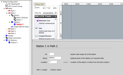
Step 2: Understanding MagneMotion Stations
In a MagneMotion system, a Station is a defined position on a path. Since Node Controllers typically control vehicles through a command that includes a vehicle ID, a Path ID, and a position value, Stations are a useful way to handle vehicle commands. You can simply tell a Vehicle to go to Station A without knowing exactly where Station A is positioned, or tell the vehicle at Station A to go to Station B without knowing which vehicle is in that exact position.
Before you start using the ICT Station AOI, it is important to know that Stations used by the PLC and Stations established in the Node Controller Configuration are two different things.
In the Configuration file you can define stations as points on paths with a specified ID. These stations are hard coded and cannot be modified without changing the configuration files. They are also not included in the information that is sent between the Node Controller and the PLC, so they are not a very useful tool for PLC controlled systems.
The stations used in the ICT library on the PLC are also defined as a position on a particular path but they are more flexible to use. These stations are defined by using the Station AOI and are only used by the PLC code. The Node Controller will have no knowledge of what these stations are or that they even exist.
For example, if station 4 is 500 mms down path 5 and the PLC tells vehicle 12 to go to station 4, the MagneMotion device handler on the PLC will send a command to the Node Controller to send vehicle 12 to 0.5 meters down path 5.
Another important thing to note is that a vehicle is only considered to be at a station when its target ID is that station and the Node Controller has confirmed that the vehicle has reached its destination. The PLC does not run any checks for vehicles near the position of a station. This means that a vehicle can be in the exact position of a station, but the station will think there is nothing there. This can be a very useful way to prevent the station from thinking it has a vehicle in the event a vehicle is routing through where a station is located but not stopping there.
Unfortunately, this also means that the Station AOI does not actually verify that the vehicle it thinks is present is actually at the station. If a vehicle is on its way to a station and you command it to go to another location via NC Host, the Station AOI will think the vehicle has arrived at its station once it has stopped, even if it is in an entirely different location. This is because it will receive a “move finished” acknowledgement from the Node Controller.
The good news is that as long as you do not command vehicles through NC host while the PLC is trying to control them through Station AOIs, the PLC device handler is sophisticated enough to keep things neat and tidy. However, be wary of using NC host commands while the PLC is controlling the Node Controller.
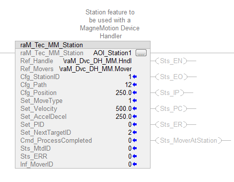
Step 3: Using the Station AOI
Much like the Path AOI, the station AOI needs the device handler tag from the \raM_DVC_DH_MM program along with the Mover tag from that same program as inputs.
Other Station AOI Inputs:
• Cfg_Station ID: The numerical ID of the station (make sure no two stations have the same ID)
• Cfg_Path ID: The ID of the path that the station is on
• Cfg_Position: The distance in mm of the station position from the beginning of the path (Make sure you do not put in a position that is longer than the actual path)
• Set_MoveType: The direction vehicles take when leaving the station to go to their next destination: 0 = Shortest Direction, 1 = Positive Direction, 2 = Negative Direction (It is usually a good idea to use Positive or Negative direction to make your station more predictable and avoid traffic issues)
• Set_Velocity: The target velocity of vehicles that leave the station in mm/s
• Set_AccelDecel: The acceleration of vehicles that leave the station in mm/s^2
• Set_PID: The PID controls for the vehicle leaving the station. PID controls are defined in the configuration file. If is fine to leave this as 0.
• Set_NextTargetID: The ID of the station the vehicle will go to after this one
• Cmd_ProccessCompleted: A command to tell the station to forward a mover onto the next station
While using the Station AOI the configuration inputs to the AOI can be changed while the system is running, but you should be careful when doing so. Changes to the station will only affect vehicles that leave the station after the change is made.
For example, if Vehicle 10 is told to go to from Station 4 to Station 5 at 500 mm/s but then the Set_Velocity of Station 4 changes to 250 mm/s before it arrives, Vehicle 10 will keep moving at 500 mm/s until it arrives at Station 5.
Additionally, if Vehicle 11 is on its way to Station 4 and the Cfg_Path of Station 4 is changed from Path 6 to Path 7, then Vehicle 11 will still go to Path 6 and Station 4 will still consider Vehicle 11 to be at its station even though they are on different paths.
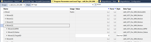
Step 4: Moving Vehicles to Stations
In order to get vehicles to move between stations, you must get a vehicle to a station first. Fortunately, this is fairly simple.
Expand the Mover tag in the raM_Dvc_DH_MM program. In the tag for TargetID, set the value to the station you want the vehicle to go to and the Device Handler will automatically send a command the Node Controller to move the vehicle to the desired station.
Now that the Station is set up and you can send vehicles there, you can start moving vehicles from one station to the next. As you can see in the snippet of code below, when bSendFromStation is toggled, whichever vehicle is at Station 1 will be sent to Station 2.
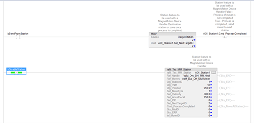
Note that Station 2 must also be configured and properly set up for this to work. There must also be a valid path that a vehicle can take to get from Station 1 to Station 2.
At this point, you must also call the station that the mover is being sent to. In the code above, if bDisableStation was on a station trying to send a vehicle to Station 1, it would make that vehicle wait in place while the station was disabled.
When moving vehicles to stations, it is very important to make sure that the vehicle has a valid route to the target station. If it does not, the target station will fault out and any other vehicles that get sent to that station will be unable to move there until the fault is clear.
To reset the error of a faulted station, go into the mover array and clear out the target ID of whichever mover caused the fault. Then stop calling the station for at least one scan, after which you can resume calling the station. This re-initializes the station and clears out the fault. In the code snippet above, toggling bDisableStation will effectively reset any path faults.
Topics to look forward to in this series:
Learn more about DMC's MagneMotion expertise and contact us to get started on your next project.